ASRock Z77 Extreme6 User Manual
ASRock Z77 Extreme6 Manual
 |
View all ASRock Z77 Extreme6 manuals
Add to My Manuals
Save this manual to your list of manuals |
ASRock Z77 Extreme6 manual content summary:
- ASRock Z77 Extreme6 | User Manual - Page 1
Z77 Extreme6 User Manual Version 1.0 Published December 2011 Copyright©2011 ASRock INC. All rights reserved. 1 - ASRock Z77 Extreme6 | User Manual - Page 2
ASRock. ASRock assumes no responsibility for any errors or omissions that may appear in this manual. With respect to the contents of this manual, ASRock does not provide warranty USA ONLY The Lithium battery adopted on this motherboard contains Perchlorate, a toxic substance controlled in Perchlorate - ASRock Z77 Extreme6 | User Manual - Page 3
HDDs ..... 52 2.19 SATA / SATA2 / SATA3 HDD Hot Plug Feature and Operation Guide 53 2.20 Driver Installation Guide 55 2.21 Installing Windows® 7 / 7 64-bit / VistaTM / VistaTM 64-bit / XP / XP 64-bit With RAID Functions 55 2.21.1 Installing Windows® XP / XP 64-bit With RAID Functions 55 2.21 - ASRock Z77 Extreme6 | User Manual - Page 4
bit Without RAID Functions 57 2.22.2 Installing Windows® 7 / 7 64-bit / VistaTM / VistaTM 64-bit Without RAID Functions 58 3 UEFI SETUP UTILITY 59 3.1 Introduction 59 3.1.1 UEFI Menu Bar 59 3.1.2 Navigation Keys 60 3.2 Main Screen 60 3.3 OC Tweaker Screen 61 3.4 Advanced Screen 66 3.4.1 CPU - ASRock Z77 Extreme6 | User Manual - Page 5
3.0 Bracket 1 x ASRock SLI_Bridge_2S Card ASRock Reminds You... To get better performance in Windows® 7 / 7 64-bit / VistaTM / VistaTM 64bit, it is recommended to set the BIOS option in Storage Configuration to AHCI mode. For the BIOS setup, please refer to the "User Manual" in our support CD for - ASRock Z77 Extreme6 | User Manual - Page 6
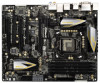
1.2 Specifications Platform CPU Chipset Memory Expansion Slot Graphics - ATX Form Factor: 12.0-in x 9.6-in, 30.5 cm x 24.4 cm - Premium Gold Capacitor design (100% Japan-made high-quality Conductive Polymer Capacitors) - Supports 3rd and 2nd Generation Intel® CoreTM i7 / i5 / i3 in LGA1155 Package - ASRock Z77 Extreme6 | User Manual - Page 7
Audio LAN Rear Panel I/O Pixel Shader 4.1, DirectX 10.1 with Intel® Sandy Bridge CPU - Max. shared memory 1760MB (see CAUTION 5) - Four VGA Output options: D-Sub, DVI-D, HDMI and DisplayPort (see CAUTION 6) - Supports HDMI 1.4a Technology with max. resolution up to 1920x1200 @ 60Hz - Supports DVI - ASRock Z77 Extreme6 | User Manual - Page 8
header - 1 x Power LED header - CPU/Chassis/Power FAN connector - 24 pin ATX power connector - 8 pin 12V power connector - SLI/XFire power connector - Front panel audio connector - 3 x USB 2.0 headers (support 6 USB 2.0 ports) - 1 x USB 3.0 header (supports 2 USB 3.0 ports) - 1 x Dr. Debug with LED - ASRock Z77 Extreme6 | User Manual - Page 9
13) - ASRock XFast LAN (see CAUTION 14) - ASRock XFast RAM (see CAUTION 15) - ASRock Crashless BIOS (see CAUTION 16) - Lucid Virtu Universal MVP (see CAUTION 17) * Lucid Virtu Universal MVP can be supported only with processors which are GPU integrated. - Hybrid Booster: - CPU Frequency - ASRock Z77 Extreme6 | User Manual - Page 10
than 4GB for the reservation for system usage under Windows® 7 / VistaTM / XP. For Windows® OS with 64-bit CPU, there is no such limitation. You can use ASRock XFast RAM to utilize the memory that Windows® cannot use. 4. Only PCIE2 and PCIE4 slots support Gen 3 speed. To run the PCI Express in Gen - ASRock Z77 Extreme6 | User Manual - Page 11
procedures of ASRock Extreme Tuning Utility (AXTU). ASRock website: http://www.asrock.com 10. ASRock Instant Flash is a BIOS flash utility embedded in Flash ROM. This convenient BIOS update tool allows you to update system BIOS without entering operating systems first like MS-DOS or Windows®. With - ASRock Z77 Extreme6 | User Manual - Page 12
LGA 775, LGA 1155 and LGA 1156. Please be noticed that not all the 775 and 1156 CPU Fan can be used. 21. ASRock XFast RAM is not supported by Microsoft® Windows® XP / XP 64-bit. Intel® Smart Connect Technology and Intel® USB 3.0 ports are not supported by Microsoft® Windows® VistaTM / VistaTM 64-bit - ASRock Z77 Extreme6 | User Manual - Page 13
supply selection, we recommend you to check with the power supply manufacturer for more details. 13 - ASRock Z77 Extreme6 | User Manual - Page 14
. Debug 2 ATX 12V Power Connector (ATX12V1) 25 Clear CMOS Jumper (CLRCMOS1) 3 SLI / XFIRE Power Connector 26 USB 2.0 Header (USB2_3, Black) 4 Chassis Fan Connector (CHA_FAN3) 27 Intel Z77 Chipset 5 Chassis Fan Connector (CHA_FAN2) 28 USB 2.0 Header (USB4_5, Black) 6 1155-Pin CPU Socket 29 - ASRock Z77 Extreme6 | User Manual - Page 15
13 12 11 1 PS/2 Keyboard/Mouse Port (Purple/Green) 10 Microphone (Pink) 2 D-Sub Port (VGA1) 11 Optical SPDIF Out Port 3 DisplayPort (DP_1) 12 USB 3.0 Ports (USB3_2_3) 4 USB 2.0 Ports (USB01) 13 IEEE 1394 Port (IEEE 1394) * 5 LAN RJ-45 Port *** 14 eSATA3 Connector 6 Central / Bass (Orange - ASRock Z77 Extreme6 | User Manual - Page 16
Primary output" to use Rear Speaker, Central/Bass, and Front Speaker, or select "Realtek HDA Audio 2nd output" to use front panel audio. *** eSATA3 connector supports SATA Gen3 in cable 1M. 16 - ASRock Z77 Extreme6 | User Manual - Page 17
by circles to secure the motherboard to the chassis. Do not over-tighten the screws! Doing so may damage the motherboard. 2.2 Pre-installation Precautions Take note of the following precautions before you install motherboard components or change any motherboard settings. 1. Unplug the power cord - ASRock Z77 Extreme6 | User Manual - Page 18
Intel 1155-Pin CPU, please follow the steps below. 1155-Pin Socket Overview Before you insert the 1155-Pin CPU into the socket, please check if the CPU surface is unclean or if there are any bent pins in the socket. Do not force to insert the CPU if returning the motherboard for after service. 18 - ASRock Z77 Extreme6 | User Manual - Page 19
key notches. orientation key notch alignment key Pin1 Pin1 orientation key notch 1155-Pin CPU alignment key 1155-Pin Socket For proper inserting, please ensure to match the two orientation key notches of the CPU with the two alignment keys of the socket. Step 3-3. Carefully place the - ASRock Z77 Extreme6 | User Manual - Page 20
fan operation or contact other components. Please be noticed that this motherboard supports Combo Cooler Option (C.C.O.), which provides flexible options to adopt three different CPU cooler types, Socket LGA 775, LGA 1155 and LGA 1156. The white throughholes are for Socket LGA 1155/1156 CPU fan - ASRock Z77 Extreme6 | User Manual - Page 21
DIMMs with 16 chips may not work on this motherboard. It is not recommended to install them on this motherboard. 6. For optimal compatibility and stability while overclocking memory frequency, it is recommended to install one memory module in DDR3_B2 slot or two memory modules in DDR3_A2 and DDR3_B2 - ASRock Z77 Extreme6 | User Manual - Page 22
notch on the DIMM matches the break on the slot. The DIMM only fits in one correct orientation. It will cause permanent damage to the motherboard and the DIMM if you force the DIMM into the slot in incorrect orientation. Step 3. Firmly insert the DIMM into the slot until the retaining - ASRock Z77 Extreme6 | User Manual - Page 23
at x8 bandwidth while PCIE5 slot will work at x4 bandwidth. 4. Please connect a chassis fan to the motherboard's chassis fan connector (CHA_FAN1, CHA_FAN2 or CHA_FAN3) when using multiple graphics cards for better thermal environment. 5. Only PCIE2 and PCIE4 slots support Gen 3 speed. To run the PCI - ASRock Z77 Extreme6 | User Manual - Page 24
is unplugged. Please read the documentation of the expansion card and make necessary hardware settings for the card before you start the installation. Remove the system unit cover (if your motherboard is already installed in a chassis). Remove the bracket facing the slot that you intend to use. Keep - ASRock Z77 Extreme6 | User Manual - Page 25
Operation Guide This motherboard supports NVIDIA® SLITM and Quad SLITM (Scalable Link Interface) technology that allows you to install up to two identical PCI Express x16 graphics cards. Currently, NVIDIA® SLITM technology supports Windows® XP / XP 64-bit / VistaTM / VistaTM 64-bit / 7 / 7 64-bit OS - ASRock Z77 Extreme6 | User Manual - Page 26
SLI_Bridge_2S Card to the goldfingers on each graphics card. Make sure the ASRock SLI_Bridge_2S Card is firmly in place. ASRock SLI_Bridge_2S Card Step4. Connect a VGA cable or a DVI cable to the monitor connector or the DVI connector of the graphics card that is inserted into - ASRock Z77 Extreme6 | User Manual - Page 27
below procedures to enable the multi-GPU feature. For Windows® XP / XP 64-bit OS: (For SLITM mode only) A. Double-click NVIDIA Settings icon on your Windows® taskbar. B. From the pop-up menu, select Set SLI and PhysX configuration. In Set PhysX GPU acceleration item, please select Enabled. In Select - ASRock Z77 Extreme6 | User Manual - Page 28
VistaTM 64-bit / 7 / 7 64-bit OS: (For SLITM and Quad SLITM mode) A. Click the Start icon on your Windows taskbar. B. From the pop-up menu, select All Programs, and then click NVIDIA Corporation. C. Select NVIDIA Control Panel tab. D. Select Control Panel tab. E. From the pop-up menu, select Set SLI - ASRock Z77 Extreme6 | User Manual - Page 29
supported by Windows® XP with Service Pack 2 / VistaTM / 7 OS. 3-way CrossFireXTM and Quad CrossFireXTM are supported by Windows® VistaTM / 7 OS only. Please check AMD's website for AMD CrossFireXTM driver updates to AMD graphics card manuals for detailed installation guide. Step 1. Insert one - ASRock Z77 Extreme6 | User Manual - Page 30
Bridge Interconnects on the top of the Radeon graphics cards. (The CrossFire Bridge is provided with the graphics card you purchase, not bundled with this motherboard. Please refer to your graphics card vendor for details.) CrossFire Bridge or Step 3. Connect the DVI monitor cable to the DVI - ASRock Z77 Extreme6 | User Manual - Page 31
identical 3-Way CrossFireXTM-ready graphics cards that are AMD certified because different types of graphics cards will not work together properly provided with the graphics card you purchase, not bundled with this motherboard. Please refer to your graphics card vendor for details.) CrossFireTM - ASRock Z77 Extreme6 | User Manual - Page 32
for AMD driver updates. Step 3. Step 4. Step 5. Install the required drivers to your system. For Windows® XP OS: A. AMD recommends Windows® XP Service Pack 2 or higher to be installed (If you have Windows® XP Service Pack 2 or higher installed in your system, there is no need to download it - ASRock Z77 Extreme6 | User Manual - Page 33
"Enable CrossFireTM", the CrossFireXTM function may not work actually. Your computer will automatically reboot. After Step 7. You can freely enjoy the benefits of CrossFireXTM, 3-Way CrossFireXTM or Quad CrossFireXTM. * CrossFireXTM appearing here is a registered for updates and details. 33 - ASRock Z77 Extreme6 | User Manual - Page 34
to this motherboard. This motherboard also provides independent display controllers for DVI-D, D-Sub, HDMI and DisplayPort to support dual VGA output I/O panel. D-Sub port DisplayPort DVI-D port HDMI port 2. If you have already installed the onboard VGA driver from our support CD to your system - ASRock Z77 Extreme6 | User Manual - Page 35
VGA card is inserted to this motherboard. 4. Install the onboard VGA driver and the add-on PCI Express VGA card driver to your system. If you have installed the drivers already, there is no need to install them again. 5. Set up a multi-monitor display. For Windows® XP / XP 64-bit OS: Right click on - ASRock Z77 Extreme6 | User Manual - Page 36
For Windows® 7 / 7 64-bit / VistaTM / VistaTM 64-bit OS: Right click the desktop, choose "Personalize", and select the "Display Settings" tab so that you can adjust the parameters of the multi-monitors according to the steps below. A. Click the number "2" icon. B. Click the items "This - ASRock Z77 Extreme6 | User Manual - Page 37
most of the chassis on the market. 3. The Multi-Angle CIR Receiver does not support Hot-Plug function. Please install it before you boot the system. * ASRock Smart Remote is only supported by some of ASRock's motherboards. Please refer to ASRock's website for the motherboard support list: http://www - ASRock Z77 Extreme6 | User Manual - Page 38
p.14, No. 25) Setting Default Clear CMOS Description Note: CLRCMOS1 parameters to default setup, please turn updating the BIOS, you must boot up the system first, and then shut it down before you do the clear-CMOS action. Please be noted that the password, date, time, user default profile, 1394 GUID - ASRock Z77 Extreme6 | User Manual - Page 39
jumper caps over the headers and connectors will cause permanent damage of the motherboard! FDD connector (33-pin FLOPPY1) (see p.14 No. 33) connectors support SATA data cables for internal storage devices. The current SATA3 interface allows up to 6.0 Gb/s data transfer rate. If the eSATA3 port on - ASRock Z77 Extreme6 | User Manual - Page 40
P-2 USB_PWR USB_PWR P-5 P+5 GND DUMMY 1 GND P+4 P-4 USB_PWR Besides two default USB 2.0 ports on the I/O panel, there are three USB 2.0 headers on this motherboard. Each USB 2.0 header can support two USB 2.0 ports. USB 3.0 Header (19-pin USB3_4_5) (see p.14, No. 12) Vbus IntA_P4_SSRXIntA_P4_SSRX - ASRock Z77 Extreme6 | User Manual - Page 41
and control of audio devices. 1. High Definition Audio supports Jack Sensing, but the panel wire on the chassis must support HDA to function correctly. Please follow the instruction in our manual and chassis manual to install your system. 2. If you use AC'97 audio panel, please install it to the - ASRock Z77 Extreme6 | User Manual - Page 42
Power LED Header (3-pin PLED1) (see p.14, No. 20 Chassis and Power Fan Connectors (4-pin CHA_FAN1) FAN_SPEED_CONTROL CHA_FAN_SPEED +12V (see p.14, No. the fan cables to the fan connectors and match the black wire to the ground pin. CHA_FAN1, CHA_FAN2 and CHA_FAN3 supports Fan Control. - ASRock Z77 Extreme6 | User Manual - Page 43
to the ground pin. Though this motherboard provides 4-Pin CPU fan (Quiet Fan) support, the 3-Pin CPU fan still can work successfully even without the fan speed control function. If you plan to connect the 3-Pin CPU fan to the CPU fan connector on this motherboard, please connect it to Pin 1-3. Pin - ASRock Z77 Extreme6 | User Manual - Page 44
I/O panel, there is one IEEE 1394 header (FRONT_1394) on this motherboard. This IEEE 1394 header can support one IEEE 1394 port. Serial port Header (9-pin COM1) (see p.14, No. 34) This COM1 header supports a serial port module. HDMI_SPDIF Header (2-pin HDMI_SPDIF1) (see p.14, No. 36 - ASRock Z77 Extreme6 | User Manual - Page 45
. Step 5 Plug the Front USB 3.0 cable into the USB 3.0 Step 6 The Front USB 3.0 Panel is ready to use. header (USB3_4_5) on the motherboard. The Installation Guide of Rear USB 3.0 Bracket Step 1 Unscrew the two screws from the Front USB 3.0 Step 2 Put the USB 3.0 cable and the rear Panel. USB - ASRock Z77 Extreme6 | User Manual - Page 46
2.13 Smart Switches The motherboard has three smart switches: power switch, reset switch and clear CMOS switch, allowing users to quickly turn on/off or reset the system to clear - ASRock Z77 Extreme6 | User Manual - Page 47
for future AMI SEC error codes Microcode not found Microcode not loaded PEI Core is started Pre-memory CPU initialization is started Pre-memory CPU initialization (CPU module specific) Pre-memory CPU initialization (CPU module specific) Pre-memory CPU initialization (CPU module specific) Pre - ASRock Z77 Extreme6 | User Manual - Page 48
Unspecified memory initialization error Memory not installed Invalid CPU type or Speed CPU mismatch CPU self test failed or possible CPU cache error CPU micro-code is not found or micro-code update is failed Internal CPU error reset PPI is not available Reserved for future AMI error codes S3 - ASRock Z77 Extreme6 | User Manual - Page 49
Services CPU DXE initialization is started CPU DXE initialization (CPU module specific) CPU DXE initialization (CPU module specific) CPU DXE initialization (CPU module specific) CPU DXE initialization (CPU DXE codes OEM DXE initialization codes Boot Device Selection (BDS) phase is started Driver - ASRock Z77 Extreme6 | User Manual - Page 50
plug Clean-up of NVRAM Configuration Reset (reset of NVRAM settings) Reserved for future AMI codes OEM BDS initialization codes CPU initialization error North Bridge initialization error South Bridge initialization error Some of the Architectural Protocols are not available PCI resource allocation - ASRock Z77 Extreme6 | User Manual - Page 51
that supports Serial ATA (SATA) / Serial ATA2 (SATA2) hard disks and RAID (RAID 0, RAID 1, RAID 5, RAID 10, Intel Rapid Storage and Intel Smart Response Technology) functions. You may install SATA / SATA2 hard disks on this motherboard for internal storage devices. This section will guide you - ASRock Z77 Extreme6 | User Manual - Page 52
action to insert and remove the SATA / SATA2 HDDs while the system is still power-on and in working condition. 2.18 Hot Plug and Hot Swap Functions for SATA3 HDDs This motherboard supports Hot Plug and Hot Swap functions for SATA3 in RAID / AHCI mode. Intel® Z77 and ASMedia ASM1061 chipsets provide - ASRock Z77 Extreme6 | User Manual - Page 53
is installed into system properly. The latest SATA / SATA2 / SATA3 driver is available on our support website: www.asrock.com 4. Make sure to use the SATA power cable & data cable, which are from our motherboard package. 5. Please follow below instructions step by step to reduce the risk of HDD - ASRock Z77 Extreme6 | User Manual - Page 54
follow below instruction sequence to process the Hot Plug, improper procedure will cause the SATA / SATA2 / SATA3 HDD damage and data loss. Step 1 Please connect SATA power cable 1x4pin end (White) to the power supply 1x4-pin cable. Step 2 Connect SATA data cable to the motherboard's SATA2 / SATA3 - ASRock Z77 Extreme6 | User Manual - Page 55
Windows® XP / XP 64-bit on your SATA / SATA2 / SATA3 HDDs with RAID functions, please follow the steps below. STEP 1: Set up UEFI. A. Enter UEFI SETUP UTILITY Advanced screen Storage Configuration. B. Set the option "SATA Mode Selection" to [RAID] for SATA2_2 to SATA2_5 and SATA3_0 and SATA3_1 ports - ASRock Z77 Extreme6 | User Manual - Page 56
.. \ RAID Installation Guide STEP 4: Install Windows® XP / XP 64-bit OS on your system. After making a SATA / SATA2 / SATA3 driver diskette and using "RAID Installation Guide" to set RAID configuration, you can start to install Windows® XP / XP 64bit on your system. At the beginning of Windows setup - ASRock Z77 Extreme6 | User Manual - Page 57
Enter UEFI SETUP UTILITY Advanced screen Storage Configuration. B. Set the option "SATA Mode Selection" to [IDE]. (For SATA2_2 to SATA2_5, SATA3_0 and SATA3_1 ports.) Set the option "ASMedia SATA3 Mode" to [IDE]. (For SATA3_A1 and SATA3_A2 ports.) STEP 2: Install Windows® XP / XP 64-bit OS on your - ASRock Z77 Extreme6 | User Manual - Page 58
SATA3_A1 and SATA3_A2 ports.) STEP 2: Install Windows® 7 / 7 64-bit / VistaTM / VistaTM 64-bit OS on your system. Using SATA / SATA2 / SATA3 HDDs without NCQ function STEP 1: Set Up UEFI. A. Enter UEFI SETUP UTILITY Advanced screen Storage Configuration. B. Set the option "SATA Mode Selection" to - ASRock Z77 Extreme6 | User Manual - Page 59
UEFI SETUP UTILITY after POST, restart the system by pressing + + , or by pressing the reset button on the system chassis. You may also restart by turning the system off and then back on. Because the UEFI software is constantly being updated, the following UEFI setup screens and - ASRock Z77 Extreme6 | User Manual - Page 60
> Load optimal default values for all the settings Save changes and exit the UEFI SETUP UTILITY Print screen Jump to the Exit Screen or exit the current screen 3.2 Main Screen When you enter the UEFI SETUP UTILITY, the Main screen will appear and display the system overview - ASRock Z77 Extreme6 | User Manual - Page 61
is [Enabled]. Configuration options: [Enabled] and [Disabled]. If you install Windows® VistaTM / 7 and want to enable this function, please set this item to [Enabled]. This item will be hidden if the current CPU does not support Intel SpeedStep technology. Please note that enabling this function may - ASRock Z77 Extreme6 | User Manual - Page 62
GT OverClocking Support. The default value is [Disabled]. DRAM Timing Configuration Load XMP Setting Use this to load XMP setting. Configuration options: [Auto], [Default], [Profile 1] and [Profile 2]. The default value is [Auto]. DRAM Frequency If [Auto] is selected, the motherboard will detect - ASRock Z77 Extreme6 | User Manual - Page 63
. The default is [Auto]. Command Rate (CR) Use this item to change Command Rate (CR) Auto/Manual setting. The default is [Auto]. DRAM tWR Use this item to change Write Recovery Time (tWR) Auto/Manual setting. The default is [Auto]. DRAM tRFC Use this item to change Refresh Cyle Time (tRFC) Auto - ASRock Z77 Extreme6 | User Manual - Page 64
to change Read to Precharge (tRTP) Auto/Manual setting. The default is [Auto]. DRAM tFAW Use this item to change Four Activate Window (tFAW) Auto/Manual setting. The default is [Auto]. DRAM tCWL Use this item to change CAS# Write Latency (tCWL) Auto/Manual setting. The default is [Auto]. ODT WR (CH - ASRock Z77 Extreme6 | User Manual - Page 65
Use this to select VCCSA Voltage. The default value is [Auto]. User Defaults In this option, you are allowed to load and save three user defaults according to your own requirements. 65 - ASRock Z77 Extreme6 | User Manual - Page 66
3.4 Advanced Screen In this section, you may set the configurations for the following items: CPU Configuration, North Bridge Configuration, South Bridge Configuration, Intel(R) Rapid Start Technology, Intel(R) Smart Connect Technology, Storage Configuration, Super IO Configuration, ACPI - ASRock Z77 Extreme6 | User Manual - Page 67
3.4.1 CPU Configuration Intel Hyper Threading Technology To enable this feature, a computer system with an Intel processor that supports Hyper-Threading technology and an operating system that includes optimization for this technology, such as Microsoft® Windows® XP / VistaTM / 7 is required. Set to - ASRock Z77 Extreme6 | User Manual - Page 68
. An IA-32 processor with "No Execute (NX) Memory Protection" can prevent data pages from being used by malicious software to execute codes. This option will be hidden if the current CPU does not support No-Excute Memory Protection. Intel Virtualization Technology When this option is set to [Enabled - ASRock Z77 Extreme6 | User Manual - Page 69
This allows you to set onboard VGA share memory feature. The default value is [Auto]. IGPU Multi-Moniter This allows you to enable or disable IGPU Multi-Moniter. The default value is [Enabled]. If you wish to install a PCI Express card under Windows® XP / VistaTM OS, please disable - ASRock Z77 Extreme6 | User Manual - Page 70
Onboard LAN feature. Onboard 1394 This allows you to enable or disable the Onboard 1394 feature. Deep Sleep Mobile platforms support Deep S4/S5 in DC only and desktop platforms support Deep S4/S5 in AC only. The default value is [Enabled in S5]. Restore on AC/Power Loss This allows you to set the - ASRock Z77 Extreme6 | User Manual - Page 71
3.4.4 Intel(R) Rapid Start Technology Intel(R) Rapid Start Technology Use this item to enable or disable Intel(R) Rapid Start Technology. Intel(R) Rapid Start Technology is a new zero power hibernation mode which allows users to resume in just 5-6 seconds. The default is [Disabled]. 71 - ASRock Z77 Extreme6 | User Manual - Page 72
(R) Smart Connect Technology Intel(R) Smart Connect Technology Use this item to enable or disable Intel(R) Smart Connect Technology. Intel(R) Smart Connect Technology keeps your e-mail and social networks, such as Twitter, Facebook, etc. updated automatically while the computer is in sleep mode. The - ASRock Z77 Extreme6 | User Manual - Page 73
Selection This item is for SATA3_0, SATA3_1 and SATA2_2 to SATA2_5 ports. Use this to select SATA mode. Configuration options: [IDE Mode], [AHCI Mode] and [RAID Mode]. The default value is [AHCI Mode]. AHCI (Advanced Host Controller Interface) supports NCQ and other new features that will improve - ASRock Z77 Extreme6 | User Manual - Page 74
We recommend to use Intel® Z77 SATA ports (SATA3_0, SATA3_1, SATA2_2, SATA2_3, SATA2_4 and SATA2_5) for your bootable devices. This will minimum your boot time and get the best performance. But if you still want to boot from ASMedia SATA3 controller, you can still enable this in UEFI. 74 - ASRock Z77 Extreme6 | User Manual - Page 75
Floppy Controller Use this item to enable or disable floppy drive controller. Serial Port Use this item to enable or disable the onboard serial port. Serial Port Address Use this item to set the address for the onboard serial port. Configuration options: [3F8h / IRQ4] and [3E8h / IRQ4]. Infrared - ASRock Z77 Extreme6 | User Manual - Page 76
the OS supports it. Check Ready Bit Use this item to enable or disable the feature Check Ready Bit. ACPI HPET Table Use this item to enable or disable ACPI HPET Table. The default value is [Enabled]. Please set this option to [Enabled] if you plan to use this motherboard to submit Windows® VistaTM - ASRock Z77 Extreme6 | User Manual - Page 77
issues, it is recommended to select [Disabled] to enter OS. [UEFI Setup Only] - USB devices are allowed to use only under UEFI setup and Windows / Linux OS. Legacy USB 3.0 Support Use this option to enable or disable legacy support for USB 3.0 devices. The default value is [Enabled]. 77 - ASRock Z77 Extreme6 | User Manual - Page 78
Event Monitoring Screen In this section, it allows you to monitor the status of the hardware on your system, including the parameters of the CPU temperature, motherboard temperature, CPU fan speed, chassis fan speed, and the critical voltage. CPU Fan 1 & 2 Setting This allows you to set CPU fan - ASRock Z77 Extreme6 | User Manual - Page 79
Screen In this section, it will display the available devices on your system for you to configure the boot settings and the boot priority. Setup Prompt Timeout This shows the number of seconds to wait for setup Count. Boot From Onboard LAN Use this item to enable or disable the Boot From Onboard - ASRock Z77 Extreme6 | User Manual - Page 80
3.7 Security Screen In this section, you may set or change the supervisor/user password for the system. For the user password, you may also clear it. 80 - ASRock Z77 Extreme6 | User Manual - Page 81
3.8 Exit Screen Save Changes and Exit When you select this option, the following message "Save configuration changes and exit setup?" will pop-out. Select [Yes] to save the changes and exit the UEFI SETUP UTILITY. Discard Changes and Exit When you select this option, the following message "Discard - ASRock Z77 Extreme6 | User Manual - Page 82
Chapter 4: Software Support 4.1 Install Operating System This motherboard supports various Microsoft® Windows® operating systems: 7 / 7 64-bit / VistaTM / VistaTM 64-bit / XP / XP 64-bit. Because motherboard settings and hardware options vary, use the setup procedures in this chapter for general - ASRock Z77 Extreme6 | User Manual - Page 83
the operating system. 1. Please make sure to use Windows® VistaTM 64-bit (with SP2 or above) or Windows® 7 64-bit (with SP1 or above). 2. Press or at system POST. Set AHCI Mode in UEFI Setup Utility > Advanced > Storage Configuration > SATA Mode. 3. Choose the item "UEFI:xxx" to - ASRock Z77 Extreme6 | User Manual - Page 84
to use Windows® VistaTM 64-bit (with SP2 or above) or Windows® 7 64-bit (with SP1 or above). 2. Copy Intel® RAID drivers into a USB flash disk. You can download the driver from ASRock's website and unzip the file into a USB flash disk OR copy the file from ASRock motherboard support CD. (please - ASRock Z77 Extreme6 | User Manual - Page 85
following the Windows® instructions. 5. Follow Windows® Installation Guide to install OS. If you install Windows® 7 64-bit / VistaTM 64-bit on a large hard disk (ex. Disk volume > 2TB), it may take more time to boot into Windows® or install driver/utilities. If you encounter this problem, you will - ASRock Z77 Extreme6 | User Manual - Page 86
B. Disable "Volume Shadow Copy" service. a. Type "computer management" in the Start Menu, then press "Enter". b. Go to "Services and Applications>Services"; Then double click "Volume Shadow Copy". 86 - ASRock Z77 Extreme6 | User Manual - Page 87
Set "Startup type" to "Disable" then Click "OK". C. Reboot your system. D. After reboot, please start to install motherboard drivers and utilities. Windows® 7 64-bit: A. Please request the hotfix KB2505454 through this link: http://support.microsoft.com/kb/2505454/ B. After installing Windows® 7 64
-
 1
1 -
 2
2 -
 3
3 -
 4
4 -
 5
5 -
 6
6 -
 7
7 -
8
-
9
-
10
-
11
-
12
-
13
-
14
-
15
-
16
-
17
-
18
-
19
-
20
-
21
-
22
-
23
-
24
-
25
-
26
-
27
-
28
-
29
-
30
-
31
-
32
-
33
-
34
-
35
-
36
-
37
-
38
-
39
-
40
-
41
-
42
-
43
-
44
-
45
-
46
-
47
-
48
-
49
-
50
-
51
-
52
-
53
-
54
-
55
-
56
-
57
-
58
-
59
-
60
-
61
-
62
-
63
-
64
-
65
-
66
-
67
-
68
-
69
-
70
-
71
-
72
-
73
-
74
-
75
-
76
-
77
-
78
-
79
-
80
-
81
-
82
-
83
-
84
-
85
-
86
-
87
 |
 |

1
Z77 Extreme6
User Manual
Version 1.0
Published December 2011
Copyright©2011 ASRock INC. All rights reserved.