Acer AB2x280 F1 Acer AB7000 Enclosure with AB2x280 F1 and AB460 F1 Blade Serve
Acer AB2x280 F1 Manual
 |
View all Acer AB2x280 F1 manuals
Add to My Manuals
Save this manual to your list of manuals |
Acer AB2x280 F1 manual content summary:
- Acer AB2x280 F1 | Acer AB7000 Enclosure with AB2x280 F1 and AB460 F1 Blade Serve - Page 1
AB7000 Series Service Guide PART NO.: PRINTED IN TAIWAN - Acer AB2x280 F1 | Acer AB7000 Enclosure with AB2x280 F1 and AB460 F1 Blade Serve - Page 2
described in this manual is sold or licensed "as is". Should the programs prove defective following their purchase, the buyer (and not Acer Inc., its distributor, or its dealer) assumes the entire cost of all necessary servicing, repair, and any incidental or consequential damages resulting from any - Acer AB2x280 F1 | Acer AB7000 Enclosure with AB2x280 F1 and AB460 F1 Blade Serve - Page 3
information related to the current topic. Alerts you to any damage that might result from doing or not doing specific actions. Gives precautionary measures to avoid possible hardware or software problems. Reminds you to do specific actions relevant to the accomplishment of procedures. iii - Acer AB2x280 F1 | Acer AB7000 Enclosure with AB2x280 F1 and AB460 F1 Blade Serve - Page 4
them. CAUTION: Do not operate the server for long periods with the access panel open or removed. Operating the server in this manner results in improper airflow and improper cooling that can lead to thermal damage. Preventing electrostatic discharge To prevent damaging the system, be aware of the - Acer AB2x280 F1 | Acer AB7000 Enclosure with AB2x280 F1 and AB460 F1 Blade Serve - Page 5
21 Acer 4X QDR InfiniBand switch module 22 Acer 4X QDR InfiniBand switch module with integrated CMM 23 InfiniBand wwitch LEDs 23 System block diagram 24 AB460 F1 mainboard block diagram 24 Mainboard 27 AB460 F1 mainboard connectors 27 Jumpers 28 Clearing CMOS 28 AB2x280 F1 mainboard - Acer AB2x280 F1 | Acer AB7000 Enclosure with AB2x280 F1 and AB460 F1 Blade Serve - Page 6
a Blade Unit 37 Removing/Replacing the blade cover 38 AB460 F1 Memory removal and installation 39 Memory Support 39 Installing DIMM Memory Modules 39 Populating Memory Slots 39 AB2x280 F1 Memory removal and installation 45 Memory Support 45 Memory Installation 45 Populating Memory Slots 45 - Acer AB2x280 F1 | Acer AB7000 Enclosure with AB2x280 F1 and AB460 F1 Blade Serve - Page 7
Table of Contents Removable Drives 74 CD/DVD Drive 75 Network Drives 75 Exit Options 76 BIOS POST codes and messages 77 BIOS POST Messages 77 BIOS POST Codes 80 Recoverable POST Errors 80 Terminal POST Errors 80 vii - Acer AB2x280 F1 | Acer AB7000 Enclosure with AB2x280 F1 and AB460 F1 Blade Serve - Page 8
Table of Contents viii - Acer AB2x280 F1 | Acer AB7000 Enclosure with AB2x280 F1 and AB460 F1 Blade Serve - Page 9
System components Blade unit components Exploded view of AB460 F1 blade module Chapter 1 Item 1 2 3 4 5 6 7 Description Blade Unit/Module SAS2/SATA Hard Drives (six per blade module) SAS2/SATA Hard Drive Bays DIMMs (system memory) Airflow Deflector CPU Heatsinks Top Cover Chapter 1 1 - Acer AB2x280 F1 | Acer AB7000 Enclosure with AB2x280 F1 and AB460 F1 Blade Serve - Page 10
Exploded view of AB2x280 F1 blade module Item 1 2 3 4 5 Description Blade Unit/Module SATA Hard Drives (2 per blade node, 4 total) DIMMs (system memory, 8 per node) CPU Heatsinks (4) Top Cover 2 Chapter 1 - Acer AB2x280 F1 | Acer AB7000 Enclosure with AB2x280 F1 and AB460 F1 Blade Serve - Page 11
System parts list 1. AB7000 system unit Category CABLE Part Name KVM CABLE CASE/COVER/ BRACKET ASSEMBLY Blade Enclosure Description KVM CABLE FOR SUPERBLADE Acer Part No. 50.R6T09.001 BLADE ENCLOSURE 6K.R6509.002 BLADE REAR GEM DUMMY MODULE DUMMY POWER SUPPLY FRONT DUMMY BLADE W/O LOGO - Acer AB2x280 F1 | Acer AB7000 Enclosure with AB2x280 F1 and AB460 F1 Blade Serve - Page 12
ENCLOSURE LED LABEL AB7000/GB7000 2. AB2x280_F1 Blade Category Blade Module Part Name AB2X280 BLADE Description AB2X280 BLADE CASE/COVER/ BRACKET ASSEMBLY AB2x280 F1 server blade chassis Acer Part No. 40.R6T09.001 40.R6T09.002 Acer Part No. TX.R6500.008 HS.R6500.001 CPU/PROCESSOR Xeon DP - Acer AB2x280 F1 | Acer AB7000 Enclosure with AB2x280 F1 and AB460 F1 Blade Serve - Page 13
Category DDR3 Registered (1.5V) DIMM Part Name Description Acer Part No. Xeon DP Dual-Core E5502 (Nehalem-EP, 1.86G, 4MB, 4.80 GT/ s QPI, DDR3-800, LGA1366, 80W, D-0, AT80602000804AA, SLBEZ) Xeon DP Dual-Core E5502 ( - Acer AB2x280 F1 | Acer AB7000 Enclosure with AB2x280 F1 and AB460 F1 Blade Serve - Page 14
PLATE 3. AB460_F1 Category Blade Module TWINBLADE LATCH MYLAR STICKER WITH ACER LOGO LEFT TWINBLADE LATCH MYLAR STICKER WITH ACER LOGO RIGHT OEM FRONT BLADE LED LABEL TWINBLADE AB2X280 F1 -RIGHT OEM FRONT BLADE LED LABEL TWINBLADE AB2X280 F1 -LEFT TWINBLADE LATCH MYLAR STICKER 40.R6509.003 WITH - Acer AB2x280 F1 | Acer AB7000 Enclosure with AB2x280 F1 and AB460 F1 Blade Serve - Page 15
Category CPU/PROCESSOR Chapter 1 Part Name Description Acer Part No. Xeon DP Quad-Core X5570 (Nehalem-EP, 2.93G, 8MB, 6.40 GT/ s QPI, DDR3-1333, LGA1366, 95W, D-0, AT80602000765AA, SLBF3) Xeon DP Quad-Core X5570 ( - Acer AB2x280 F1 | Acer AB7000 Enclosure with AB2x280 F1 and AB460 F1 Blade Serve - Page 16
HEATSINK - A_GB460 Description Passive CPU Heatsink for Intel B810 Blade Acer Part No. HI.R6200.001 MAINBOARD AB460 F1 MBw/ Tylersburg C2 MB.R630F.001 MYLAR NAME PLATE LATCH MYLAR STICKER WITH ACER LOGO - LEFT LATCH MYLAR STICKER WITH ACER LOGO - RIGHT OEM FRONT BLADE LED LABEL AB460 LATCH - Acer AB2x280 F1 | Acer AB7000 Enclosure with AB2x280 F1 and AB460 F1 Blade Serve - Page 17
or more of the following procedures: • Extend the server from the rack If you are performing service procedures in the rack cabinet, you can use the locking feature of the rack rails to support the server and gain access to internal components. For more information about telco rack solutions, refer - Acer AB2x280 F1 | Acer AB7000 Enclosure with AB2x280 F1 and AB460 F1 Blade Serve - Page 18
Extend the server from the rack 1. If the server is screwed into the rack, remove the screws and set them aside. 10 Chapter 2 - Acer AB2x280 F1 | Acer AB7000 Enclosure with AB2x280 F1 and AB460 F1 Blade Serve - Page 19
2. Grasp the handles and extend the server from the rack. WARNING:To reduce the risk of personal injury or equipment damage, be sure that the rack is adequately stabilized before extending a component from the rack. 3. After performing the installation or maintenance procedure, slide the server - Acer AB2x280 F1 | Acer AB7000 Enclosure with AB2x280 F1 and AB460 F1 Blade Serve - Page 20
Power down the server WARNING: To reduce the risk of personal injury, electric shock, or damage to the equipment, remove the power cord to remove power from the server. The front panel Power On/Standby button does not completely shut off system power. Portions of the power supply and some internal - Acer AB2x280 F1 | Acer AB7000 Enclosure with AB2x280 F1 and AB460 F1 Blade Serve - Page 21
Infiniband switch Gigabit Ethernet switch Management module Power supply module Value Up to 10 hot-plug AB460 and/or ABx280 F1 server blades Supports both Intel and AMD based server blades Power LED, Fault LED Up to two hot-plug 4x QDR IB switches Up to two hot-plug - Acer AB2x280 F1 | Acer AB7000 Enclosure with AB2x280 F1 and AB460 F1 Blade Serve - Page 22
ABx2 280 F1 blade specifications Specifications (per node) Processor socket Processor support Core logic chipsets LAN controller Memory controller SATA VGA controller I/O subsystem Memory Media storage Status LED indicators Thermal solution Value Two Intel 1366-pin LGA - Acer AB2x280 F1 | Acer AB7000 Enclosure with AB2x280 F1 and AB460 F1 Blade Serve - Page 23
Depth x Height Value 7U 447 mm (17.6 in) X 737 mm (29 in) 310 mm (12.25 in) Weight AB460 F1 blade dimensions Width x Depth x Height Weight AB2x280 F1 blade dimensions Width x Depth x Height Weight • 100.2 kg approximately (standard configuration with one server blade, one CMM, one Ethernet switch - Acer AB2x280 F1 | Acer AB7000 Enclosure with AB2x280 F1 and AB460 F1 Blade Serve - Page 24
16 Chapter 3 - Acer AB2x280 F1 | Acer AB7000 Enclosure with AB2x280 F1 and AB460 F1 Blade Serve - Page 25
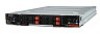
System appearance Front panel (with AB460 F1 blades included) Chapter 4 Front panel LED indicators Enclosure power supply LED descriptions are shown in the following table . LED Power Status LED (left LED) Fault - Acer AB2x280 F1 | Acer AB7000 Enclosure with AB2x280 F1 and AB460 F1 Blade Serve - Page 26
Blade control panel AB460 F1 Item Function 1 Power Button 2 KVM Button 3 Power LED State N/A N/A Green Orange 4 KVM/ID LED Blue Flashing Blue 5 Network/IB LED Flashing Green Flashing Orange 6 System - Acer AB2x280 F1 | Acer AB7000 Enclosure with AB2x280 F1 and AB460 F1 Blade Serve - Page 27
AB2x280 F1 Item Function State 1 Power Button N/A 2 KVM Button N/A 3 Power LED Green Orange 4 KVM/ID LED Blue Flashing Blue 5 Network/IB Flashing Green LED Flashing Orange 6 System - Acer AB2x280 F1 | Acer AB7000 Enclosure with AB2x280 F1 and AB460 F1 Blade Serve - Page 28
Rear panel (with 1Gb/10Gb Ethernet module and CMM included) Rear modules Bay No. Module 1 (top) 1G/10Gb Ethernet Switch Module 1 (bottom) 1G/10Gb Ethernet Switch Module (installed for Ethernet module redundancy) 2 (top) Dummy 3 (top)1 Chassis Management Module (CMM) 2+3 (top)1 4xQDR( - Acer AB2x280 F1 | Acer AB7000 Enclosure with AB2x280 F1 and AB460 F1 Blade Serve - Page 29
7 Reset Button - resets User Name and Password, IP Address and Acer Address to their default values. 8 Module Release Handle 9 USB 2.0/1.1 of module) Feature Management Capabilities Ports Basic Functions Supported System Management Power Consumption Operating System Description Can manage - Acer AB2x280 F1 | Acer AB7000 Enclosure with AB2x280 F1 and AB460 F1 Blade Serve - Page 30
Acer 4X QDR InfiniBand switch module Item 1 2 3 4 5 6 7 Description System error. Fault LED (Red)* System status. Ready LED (Green)† External InfiniBand Port (16 QSFP ports for Q3636 - Acer AB2x280 F1 | Acer AB7000 Enclosure with AB2x280 F1 and AB460 F1 Blade Serve - Page 31
Acer 4X QDR InfiniBand switch module with integrated CMM Item 1 2 3 4 5 6 7 8 9 10 Description System failed Switch is properly booted and operational Switch has power and is operational There is a problem with the power being supplied to the switch. Physical link established Physical link error, - Acer AB2x280 F1 | Acer AB7000 Enclosure with AB2x280 F1 and AB460 F1 Blade Serve - Page 32
System block diagram AB460 F1 mainboard block diagram 24 Chapter 4 - Acer AB2x280 F1 | Acer AB7000 Enclosure with AB2x280 F1 and AB460 F1 Blade Serve - Page 33
AB2x280 F1 mainboard block diagram Chapter 4 25 - Acer AB2x280 F1 | Acer AB7000 Enclosure with AB2x280 F1 and AB460 F1 Blade Serve - Page 34
26 Chapter 4 - Acer AB2x280 F1 | Acer AB7000 Enclosure with AB2x280 F1 and AB460 F1 Blade Serve - Page 35
general information on changing jumper settings as well as specific jumper configuration for individual boards in the system. AB460 F1 mainboard connectors Item 1 2 3 4 5 6 Description Item LGA 1366 CPU Sockets 7 DIMM Slots 8 6 SAS2/SATA Hard Drive Bays 9 InfiniBand Connectors (for - Acer AB2x280 F1 | Acer AB7000 Enclosure with AB2x280 F1 and AB460 F1 Blade Serve - Page 36
CMOS and will also clear any passwords. JBT1 consists of two contact pads located near the BIOS chip (refer to item 12 in the AB460 F1 mainboard). 1. First power down the blade and remove it from the enclosure. 2. Remove the blade cover to access the mainboard (see "Removing/Replacing the blade - Acer AB2x280 F1 | Acer AB7000 Enclosure with AB2x280 F1 and AB460 F1 Blade Serve - Page 37
AB2x280 F1 mainboard connectors Item Description 1 CPU Sockets 2 DIMM Slots 3 Space for 2.5" SATA Hard Drive 4 Gbx Connector (for power and logic to backplane) 5 BIOS Chip 6 Onboard Battery - Acer AB2x280 F1 | Acer AB7000 Enclosure with AB2x280 F1 and AB460 F1 Blade Serve - Page 38
. Clearing CMOS JPT1 is used to clear CMOS and will also clear any passwords. JPT1 consists of two contact pads (item 11 in the AB2x280 F1 mainboard). 1. First power down the blade and remove it from the enclosure. 2. Remove the blade cover to access the mainboard (see "Removing/Replacing the - Acer AB2x280 F1 | Acer AB7000 Enclosure with AB2x280 F1 and AB460 F1 Blade Serve - Page 39
chapter contains step-by-step procedures on how to disassemble the server system for maintenance and troubleshooting. To disassemble the server, please pay attention to each section's instruction and tools needed. NOTE: The screws for the different components vary in size. During the disassembly - Acer AB2x280 F1 | Acer AB7000 Enclosure with AB2x280 F1 and AB460 F1 Blade Serve - Page 40
3. Press and pull the two-piece handle lock (1) and pull the handle in the direction indicated (2). Pull out the power supply module (3). Installing a Power Supply 1. Insert a replacement unit into the empty power bay with the handle to the left. WARNING:This left/right orientation depends on the - Acer AB2x280 F1 | Acer AB7000 Enclosure with AB2x280 F1 and AB460 F1 Blade Serve - Page 41
been installed and the handle locked, it will turn on and a POST test will run to verify it is working properly. If there are no problems the blue Init. OK LED on the module will illuminate and you will see an OK under INITIATED in the GBE SWITCH screen of the - Acer AB2x280 F1 | Acer AB7000 Enclosure with AB2x280 F1 and AB460 F1 Blade Serve - Page 42
On HDD Access HDD Failure HDD Rebuild HDD Locate (Blue) ON Blink OFF Blink OFF (Red) One Blink Red OFF ON OFF ON AB2x280 F1 Hard Disk Drives The AB2x280 F1 blade unit accommodates up to two 2.5" SATA hard disk drives per node which are mounted in drive "carriers". The drives are hot-swappable - Acer AB2x280 F1 | Acer AB7000 Enclosure with AB2x280 F1 and AB460 F1 Blade Serve - Page 43
AB2x280 F1 HDD LED Indicators Status Power On HDD Access HDD Rebuild (Blue) ON OFF Blink OFF Blink OFF (Red) Removing a hard drive carrier 1. Locate the colored " - Acer AB2x280 F1 | Acer AB7000 Enclosure with AB2x280 F1 and AB460 F1 Blade Serve - Page 44
4. Secure the drive to the carrier with four screws as shown. 5. Insert the drive carrier into its slot keeping the Open button at the bottom. When the carrier reaches the rear of the bay the release handle will retract. 6. Push the handle in until you hear the carrier click into its locked position - Acer AB2x280 F1 | Acer AB7000 Enclosure with AB2x280 F1 and AB460 F1 Blade Serve - Page 45
Installing a Blade Unit Make sure the cover of the blade unit has been replaced first before installing a blade unit in the enclosure. 1. Slowly push the blade unit into its bay with the handles fully pulled out. 2. When the blade stops, push the handles back in to their locked position, making sure - Acer AB2x280 F1 | Acer AB7000 Enclosure with AB2x280 F1 and AB460 F1 Blade Serve - Page 46
Removing/Replacing the blade cover 1. Remove the blade unit from the enclosure (see "Removing the blade unit" above). 2. Depress the two buttons on the cover while pushing the cover toward the rear of the blade unit. When it stops, lift the cover off the blade unit. 3. To replace the cover, fit the - Acer AB2x280 F1 | Acer AB7000 Enclosure with AB2x280 F1 and AB460 F1 Blade Serve - Page 47
to prevent any possible damage. Memory Support The AB460 F1 blade module supports up to 192 GB/48 GB of supported, so you may populate any number of DIMM slots. Populating three slots at a time (DIMM1A + DIMM2A+ DIMM3A, etc.) with memory modules of the same size and of the same type will result - Acer AB2x280 F1 | Acer AB7000 Enclosure with AB2x280 F1 and AB460 F1 Blade Serve - Page 48
AB460 F1 DIMM Numbering 40 Chapter 6 - Acer AB2x280 F1 | Acer AB7000 Enclosure with AB2x280 F1 and AB460 F1 Blade Serve - Page 49
Independent Mode: Single Processor Configuration Total Capacity 1GB 2GB 3GB 4GB 6GB 2GB 4GB 6GB 8GB 12GB 4GB 8GB 12GB 16GB 24GB 8GB 16GB 24GB 32GB 48GB 16GB 32GB 48GB 64GB 96GB DIMM 1B 1GB 1GB 2GB 2GB 4GB 4GB 8GB 8GB 16GB 16GB DIMM 1A 1GB 1GB 1GB 1GB 1GB 2GB 2GB 2GB 2GB 2GB 4GB 4GB 4GB 4GB 4GB - Acer AB2x280 F1 | Acer AB7000 Enclosure with AB2x280 F1 and AB460 F1 Blade Serve - Page 50
Total Capacity DIMM 24GB 32GB 36GB 48GB 16GB 24GB 32GB 48GB 64GB 72GB 96GB 32GB 48GB 64GB 96GB 128GB 144GB 192GB 1B 4GB 4GB 4GB 8GB 8GB 8GB 16GB 16GB 16GB 1A 4GB 4GB 4GB 4GB 8GB 8GB 8GB 8GB 8GB 8GB 8GB 16GB 16GB 16GB 16GB 16GB 16GB 16GB CPU1 2B 2A 4GB 4GB 4GB 4GB 4GB 4GB 4GB 8GB 8GB 8GB - Acer AB2x280 F1 | Acer AB7000 Enclosure with AB2x280 F1 and AB460 F1 Blade Serve - Page 51
Mirroring or Lockstep Mode: Dual processor configuration Total Capacity CPU1 CPU2 DIMM 1B 1A 2B 2A 3B 3A 1B 1A 2B 2A 3B 3A 2GB 1GB 1GB 4GB 1GB 1GB 1GB 1GB 6GB 1GB 1GB 1GB 1GB 1GB 1GB 8GB 1GB 1GB 1GB 1GB 1GB 1GB 1GB 1GB 4GB 2GB 2GB 8GB 2GB 2GB 2GB 2GB - Acer AB2x280 F1 | Acer AB7000 Enclosure with AB2x280 F1 and AB460 F1 Blade Serve - Page 52
DIMM slot to be populated. A "---" indicates that the DIMM slot should be left unpopulated. NOTE: Though multiple DIMM memory module types and speeds may be supported, you need to use DIMM memory modules of the same speed and type. 44 Chapter 6 - Acer AB2x280 F1 | Acer AB7000 Enclosure with AB2x280 F1 and AB460 F1 Blade Serve - Page 53
The mainboard of a AB2x280 F1 blade module has eight memory slots per node. Both interleaved and noninterleaved memory are supported, so you may populate any number of DIMM slots. Populating slots at the same time with memory modules of the same size and of the same type will result in three-channel - Acer AB2x280 F1 | Acer AB7000 Enclosure with AB2x280 F1 and AB460 F1 Blade Serve - Page 54
Memory Population The node has eight DIMM slots. Each CPU controls four DIMM slots. The DIMM slots support three channel DDR3-1333 registered/unbuffered ECC memory modules. The farthest socket to CPU is socket A (in blue color), while the nearest one is socket B ( - Acer AB2x280 F1 | Acer AB7000 Enclosure with AB2x280 F1 and AB460 F1 Blade Serve - Page 55
Independent Mode: Dual Processor Configuration Total Capacity CPU 1 DIMM 1B 1A 2A 3A 1B 2GB 1GB 3GB 1GB 1GB 1GB 4GB 1GB 1GB 6GB 1GB 1GB 1GB 8GB 1GB 1GB 1GB 1GB 1GB 4GB 2GB 6GB 2GB 2GB 2GB 8GB 2GB 2GB 12GB 2GB 2GB 2GB 16GB 2GB 2GB 2GB 2GB 2GB 8GB 4GB - Acer AB2x280 F1 | Acer AB7000 Enclosure with AB2x280 F1 and AB460 F1 Blade Serve - Page 56
Mirroring or Lockstep mode: Dual Processor Configuration Total Capacity DIMM 2GB 4GB 4GB 8GB 8GB 16GB 16GB 32GB 32GB 64GB CPU1 1B 1A 2A 3A 1GB 1GB 1GB 1GB 2GB 2GB 2GB 2GB 4GB 4GB 4GB 4GB 8GB 8GB 8GB 8GB 16GB 16GB 16GB 16GB CPU2 1B 1A 2A 3A 1GB 1GB 2GB 2GB 4GB 4GB - Acer AB2x280 F1 | Acer AB7000 Enclosure with AB2x280 F1 and AB460 F1 Blade Serve - Page 57
the processor. Set the heatsink aside and upside-down so that nothing comes into contact with the thermal grease on its underside. AB2x280 F1 AB460 F1 Installing the heatsink 1. To install the heatsink, apply thermal grease to the top of the processor. (If reinstalling a heatsink, first clean off - Acer AB2x280 F1 | Acer AB7000 Enclosure with AB2x280 F1 and AB460 F1 Blade Serve - Page 58
from the socket, then lift the silver cover plate and remove the processor. WARNING:This action should only be performed by a trained service technician. Installing a Processor 1. If present, remove the protective black PnP cap from the processor socket. 2. Raise the lever of the processor socket - Acer AB2x280 F1 | Acer AB7000 Enclosure with AB2x280 F1 and AB460 F1 Blade Serve - Page 59
Confirm that you have the correct card and three screws. 2. Following the instructions, remove the blade module and open the cover to access the mainboard. attaching the card to the two connectors. 4. Using a Phillips screw driver, secure and tighten each screw one at a time. Do not overtighten - Acer AB2x280 F1 | Acer AB7000 Enclosure with AB2x280 F1 and AB460 F1 Blade Serve - Page 60
Rackmount installation procedure This section provides information on installing the AB7000 into a rack. There are a variety of rack units on the market, meaning the procedure may differ slightly. Refer to the Enclosure Template that was included with the system for help. Rack Mounting Hardware The - Acer AB2x280 F1 | Acer AB7000 Enclosure with AB2x280 F1 and AB460 F1 Blade Serve - Page 61
5. (Optional step) Add the front left and right handles to the enclosure using five screws to secure each handle. Install a thumbscrew through the bottom hole of each handle. NOTE: These handles are optional and need only be installed when mounting the system into a short rack. When mounting into a - Acer AB2x280 F1 | Acer AB7000 Enclosure with AB2x280 F1 and AB460 F1 Blade Serve - Page 62
8. The enclosure is now securely installed in the rack. 54 Chapter 6 - Acer AB2x280 F1 | Acer AB7000 Enclosure with AB2x280 F1 and AB460 F1 Blade Serve - Page 63
drivers used for components you have installed in your system, such as video drivers, network drivers, and SCSI drivers short out power. 4. If the problem is not evident, continue with System the system cover. For instructions on removing system cover, refer supported. 10. Replace the system cover. - Acer AB2x280 F1 | Acer AB7000 Enclosure with AB2x280 F1 and AB460 F1 Blade Serve - Page 64
completes, the system will reboot automatically. The system will show the result of the recovery process once it completes. BIOS Updates It may , it is recommended that you not update BIOS if you are not experiencing problems with a blade module. There are several methods you may use to upgrade - Acer AB2x280 F1 | Acer AB7000 Enclosure with AB2x280 F1 and AB460 F1 Blade Serve - Page 65
. Each main BIOS menu option is described in this manual. The Main BIOS setup menu screen has two main NOTE: The BIOS has default text messages built in. Acer retains the option to include, omit or change any of setup navigation process. These keys include , , , and arrow keys - Acer AB2x280 F1 | Acer AB7000 Enclosure with AB2x280 F1 and AB460 F1 Blade Serve - Page 66
Main setup When you first enter the BIOS setup utility, you will enter the main setup screen. You can always return to the main setup screen by selecting the main tab on the top of the screen. The main BIOS setup screen is shown below.System Overview System Time/System Date Use this option to - Acer AB2x280 F1 | Acer AB7000 Enclosure with AB2x280 F1 and AB460 F1 Blade Serve - Page 67
: Sets the display mode for Option ROM. Bootup Num-Lock: Selects the Power-on state for Numlock key. Wait For 'F1' If Error: Forces the system to wait until the key is pressed if an error occurs. Interrupt 19 Capture: Interrupt 19 is the software interrupt that handles the boot disk - Acer AB2x280 F1 | Acer AB7000 Enclosure with AB2x280 F1 and AB460 F1 Blade Serve - Page 68
voltage during a Halt State. IMPORTANT:The following feature is only available if supported by the processor and/or operating system. Hardware Prefetcher: If set to Enabled, the hardware prefetcher will prefetch streams of data and instructions from the main memory to the L2 cache in the forward or - Acer AB2x280 F1 | Acer AB7000 Enclosure with AB2x280 F1 and AB460 F1 Blade Serve - Page 69
an attack. IMPORTANT:The following feature is only available if supported by the processor and/or operating system. Simultaneous Multi-Threading : Set to Enabled to use simultaneous multi-threading technology, which will result in increased CPU performance. Active Processor Cores: Set to Enabled to - Acer AB2x280 F1 | Acer AB7000 Enclosure with AB2x280 F1 and AB460 F1 Blade Serve - Page 70
Advanced Chipset Control The items included in the Advanced Settings submenu are listed below: CPU Bridge configuration QPI Links Speed: This feature selects QPI data transfer speed. IMPORTANT:The following feature is only available when QPI Links Speed is set to Full Speed. QPI Frequency: This - Acer AB2x280 F1 | Acer AB7000 Enclosure with AB2x280 F1 and AB460 F1 Blade Serve - Page 71
accesses. This feature reduces or increases the frequency the system prefetches data. Intel VT-d: Select Enabled to enable Intel Virtualization Technology support for Direct I/O VT-d by reporting the I/O device assignments to VMM through the DMAR ACPI Tables. This feature offers fully-protected - Acer AB2x280 F1 | Acer AB7000 Enclosure with AB2x280 F1 and AB460 F1 Blade Serve - Page 72
inhibits the coalesce feature. Please refer to your add-on card user guide for the desired setting. South Bridge configuration This feature allows you to ports to enable. Legacy USB Support: Select Enabled to use Legacy USB devices. If set to Auto, legacy USB support will be automatically enabled if - Acer AB2x280 F1 | Acer AB7000 Enclosure with AB2x280 F1 and AB460 F1 Blade Serve - Page 73
system must be equipped with a 48-bit LBA mode addressing. If not, contact your manufacturer or install an ATA/133 IDE controller card that supports 48-bit LBA mode. • Block (Multi-Sector Transfer) - Block Mode boosts the IDE drive performance by increasing the amount of data transferred. Only 512 - Acer AB2x280 F1 | Acer AB7000 Enclosure with AB2x280 F1 and AB460 F1 Blade Serve - Page 74
Select Auto to allow the BIOS to automatically detect hard disk drive support. • 32Bit Data Transfer - Select Enable to enable the function of is not required for system boot if your system has an oerating system that supports Plug & Play.) Select No to allow the BIOS to configure all devices in - Acer AB2x280 F1 | Acer AB7000 Enclosure with AB2x280 F1 and AB460 F1 Blade Serve - Page 75
Features: The options are ACPI v1.0, ACPI v2.0 and ACPI v3.0. Please refer to ACPI's website for further explanation: http:// www.acpi.info/. ACPI APIC Support: Select Enabled to include the ACPI APIC Table Pointer in the RSDT pointer list. NOTE: Only available when ACPI is enabled on an ACPI-aware - Acer AB2x280 F1 | Acer AB7000 Enclosure with AB2x280 F1 and AB460 F1 Blade Serve - Page 76
available when ACPI is enabled on an ACPI-aware operating system. NUMA Support: Uses Non-Uniform Memory Access to improve CPU performance. High Performance on other timestamp calculation devices, such as an x86 RDTSC Instruction embedded in the CPU. The High Performance Event Timer is used - Acer AB2x280 F1 | Acer AB7000 Enclosure with AB2x280 F1 and AB460 F1 Blade Serve - Page 77
Security The BIOS provides a Supervisor and a User password. If you use both passwords, the Supervisor password must be set first. Supervisor Password: This item indicates if a supervisor password has been entered for the system. Clear means such a password has not been used and Set means a - Acer AB2x280 F1 | Acer AB7000 Enclosure with AB2x280 F1 and AB460 F1 Blade Serve - Page 78
Static (Static Allocation) to allow the host server to allocate an IP address based on a table containing MAC Address/IP Address pairs that are manually entered (such as by a network administrator). Only clients with a MAC address listed in the MAC/IP Address Table will be assigned an IP address - Acer AB2x280 F1 | Acer AB7000 Enclosure with AB2x280 F1 and AB460 F1 Blade Serve - Page 79
, 0 to 9, A, B, C, D, E, F) separated by dots. (e.g., 00.30.48.D0.D4.60). Remote Access Configuration Remote Access: This allows you to enable Remote Access support. If Remote Access is set to Enabled, the following items will be displayed: Serial Port Number: This feature allows the user to decide - Acer AB2x280 F1 | Acer AB7000 Enclosure with AB2x280 F1 and AB460 F1 Blade Serve - Page 80
Event Log Configuration View Event Log: View the System Event Log. Mark All Events as Read: Marks all events as read. Clear Event Log: This option clears the Event Log memory of all messages. 72 Chapter 8 - Acer AB2x280 F1 | Acer AB7000 Enclosure with AB2x280 F1 and AB460 F1 Blade Serve - Page 81
Boot This submenu allows you to configure boot settings for the system. Boot Device Priority This feature allows you to specify the sequence of priority for the Boot Device. • 1st Boot Device • 2nd Boot Device • 3rd Boot Device • 4th Boot Device Chapter 8 73 - Acer AB2x280 F1 | Acer AB7000 Enclosure with AB2x280 F1 and AB460 F1 Blade Serve - Page 82
Hard Disk Drives This feature allows you to specify the boot sequence from all available hard disk drives. The settings are Disabled and a list of all hard disk drives that have been detected. • 1st Drive • 2nd Drive • 3rd Drive Removable Drives This feature allows you to specify the boot sequence - Acer AB2x280 F1 | Acer AB7000 Enclosure with AB2x280 F1 and AB460 F1 Blade Serve - Page 83
CD/DVD Drive This feature allows you to specify the boot sequence from all available removable drives. Network Drives This feature allows you to specify the boot sequence from available network drives. Chapter 8 75 - Acer AB2x280 F1 | Acer AB7000 Enclosure with AB2x280 F1 and AB460 F1 Blade Serve - Page 84
Exit Options Select the Exit tab from the BIOS Setup Utility screen to enter the Exit BIOS Setup screen. Save Changes and Exit: When you have completed the system configuration changes, select this option to leave the BIOS Setup Utility and reboot the computer, so the new system configuration - Acer AB2x280 F1 | Acer AB7000 Enclosure with AB2x280 F1 and AB460 F1 Blade Serve - Page 85
Chapter 9 BIOS POST codes and messages BIOS POST Messages During the Power-On Self-Test (POST), the BIOS will check for problems. If a problem is found, the BIOS will activate an alarm or display a message. The following is a list of such BIOS messages. BIOS Message Description Failure Fixed Disk - Acer AB2x280 F1 | Acer AB7000 Enclosure with AB2x280 F1 and AB460 F1 Blade Serve - Page 86
for offset address of the failure in System, Extended, or Shadow memory. Fixed Disk n Fixed disk n (0-3) identified. Invalid System Configuration Data Problem with NVRAM (CMOS) data. I/O device IRQ conflict I/O device IRQ conflict error. PS/2 Mouse Boot Summary Screen: PS/2 Mouse installed - Acer AB2x280 F1 | Acer AB7000 Enclosure with AB2x280 F1 and AB460 F1 Blade Serve - Page 87
the address and display it on the screen. If it cannot locate the address, it displays ????. Press to resume, to Setup, for previous Displayed after any recoverable error message. Press to start the boot process or to enter Setup and change the settings. Press to - Acer AB2x280 F1 | Acer AB7000 Enclosure with AB2x280 F1 and AB460 F1 Blade Serve - Page 88
and terminal. Recoverable POST Errors When a recoverable type of error occurs during POST, the BIOS will display an POST code that describes the problem. BIOS may also issue one of the following beep codes: • One long and two short beeps - video configuration error • One repetitive long beep - Acer AB2x280 F1 | Acer AB7000 Enclosure with AB2x280 F1 and AB460 F1 Blade Serve - Page 89
values Initialize extended memory for RomPilot Initialize interrupt vectors POST device initialization 2-1-2-3 Check ROM copyright notice Initialize I20 support Check video configuration against CMOS Initialize PCI bus and devices Initialize all video adapters in system QuietBoot start (optional - Acer AB2x280 F1 | Acer AB7000 Enclosure with AB2x280 F1 and AB460 F1 Blade Serve - Page 90
70h 72h 76h 7Ch 7Dh 7Eh 80h 81h 82h 83h 84h 85h 86h 87h 88h 89h 82 Description 2-2-3-1 Test for unexpected interrupts Initialize POST display service Display prompt ,ÄúPress F2 to enter SETUP,Äù Disable CPU cache Test RAM between 512 and 640 kB Test extended memory Test extended memory address - Acer AB2x280 F1 | Acer AB7000 Enclosure with AB2x280 F1 and AB460 F1 Blade Serve - Page 91
Post Code 8Ah 8Bh 8Ch 8Fh 90h 91h 92h 93h 95h 96h 98h 99h 9Ah 9Ch 9Dh 9Eh 9Fh A0h A2h A4h A8h AAh ACh AEh B0h B1h B2h B4h B5h B6h B7h B9h Description Initialize Extended BIOS Data Area Test and initialize PS/2 mouse Initialize floppy controller Determine number of ATA drives (optional) Initialize - Acer AB2x280 F1 | Acer AB7000 Enclosure with AB2x280 F1 and AB460 F1 Blade Serve - Page 92
Post Code BAh BBh BCh BDh BEh BFh C0h C1h C2h C3h C4h C5h C6h C7h C8h C9h CAh CBh CCh CDh CEh D2h Description Initialize SMBIOS Initialize PnP Option ROMs Clear parity checkers Display MultiBoot menu Clear screen (optional) Check virus and backup reminders Try to boot with INT 19 Initialize POST - Acer AB2x280 F1 | Acer AB7000 Enclosure with AB2x280 F1 and AB460 F1 Blade Serve - Page 93
Post Code E7h E8h E9h EAh EBh ECh EDh EEh EFh F0h F1h F2h F3h F4h F5h F6h F7h Description Go to BIOS Set Huge Segment Initialize Multi Processor Initialize OEM special code Initialize PIC and DMA Initialize Memory type Initialize Memory size Shadow Boot Block System memory test Initialize interrupt - Acer AB2x280 F1 | Acer AB7000 Enclosure with AB2x280 F1 and AB460 F1 Blade Serve - Page 94
86 Chapter 9