Acer AcerPower Sc Power Sc User's Guide - Page 57
Acer AcerPower Sc Manual
 |
View all Acer AcerPower Sc manuals
Add to My Manuals
Save this manual to your list of manuals |
Page 57 highlights
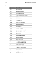
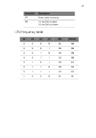
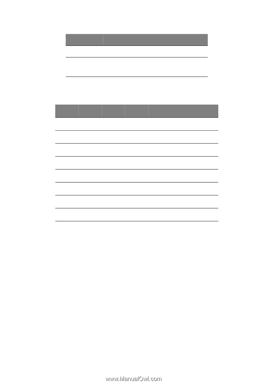
47 Connector JP7 JP9 Description Power switch connector 1-2: set CN21 as slave 2-3: set CN21 as Master CPU frequency table S4 0 0 0 0 0 0 0 1 S3 0 0 0 0 1 1 1 0 S2 0 0 1 1 0 1 1 0 S1 0 1 0 1 1 0 1 0 CPU 66 100 150 133 100 100 133 66 SDRAM 100 100 100 100 133 150 133 66
-
 1
1 -
2
-
3
-
4
-
5
-
6
-
7
-
8
-
9
-
10
-
11
-
12
-
13
-
14
-
15
-
16
-
17
-
18
-
19
-
20
-
21
-
22
-
23
-
24
-
25
-
26
-
27
-
28
-
29
-
30
-
31
-
32
-
33
-
34
-
35
-
36
-
37
-
38
-
39
-
40
-
41
-
42
-
43
-
44
-
45
-
46
-
47
-
48
-
49
-
50
-
51
-
 52
52 -
 53
53 -
 54
54 -
 55
55 -
 56
56 -
 57
57 -
 58
58 -
 59
59 -
 60
60 -
 61
61 -
 62
62 -
63
-
64
-
65
-
66
-
67
-
68
 |
 |
47
CPU frequency table
JP7
Power switch connector
JP9
1-2: set CN21 as slave
2-3: set CN21 as Master
S4
S3
S2
S1
CPU
SDRAM
0
0
0
0
66
100
0
0
0
1
100
100
0
0
1
0
150
100
0
0
1
1
133
100
0
1
0
1
100
133
0
1
1
0
100
150
0
1
1
1
133
133
1
0
0
0
66
66
Connector
Description