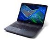
Acer Aspire 7530 Aspire 7230/7530/7530G Service Guide
Acer Aspire 7530 Manual
 |
View all Acer Aspire 7530 manuals
Add to My Manuals
Save this manual to your list of manuals |
Acer Aspire 7530 manual content summary:
- Acer Aspire 7530 | Aspire 7230/7530/7530G Service Guide - Page 1
Aspire 7230/7530/7530G Series Service Guide Service guide files and updates are available on the ACER/CSD web; for more information, please refer to http://csd.acer.com.tw PRINTED IN TAIWAN - Acer Aspire 7530 | Aspire 7230/7530/7530G Service Guide - Page 2
Revision History Please refer to the table below for the updates made on Aspire 7230/7530/7530G Series service guide. Date Chapter Updates II - Acer Aspire 7530 | Aspire 7230/7530/7530G Service Guide - Page 3
by any means, electronic, mechanical, magnetic, optical, chemical, manual or otherwise, without the prior written permission of Acer Incorporated. Disclaimer The information in this guide is subject to change without notice. Acer Incorporated makes no representations or warranties, either expressed - Acer Aspire 7530 | Aspire 7230/7530/7530G Service Guide - Page 4
appear on screen. NOTE WARNING CAUTION IMPORTANT Gives bits and pieces of additional information related to the current topic. Alerts you to any damage that might result from doing or not doing specific actions. Gives precautionary measures to avoid possible hardware or software problems. Reminds - Acer Aspire 7530 | Aspire 7230/7530/7530G Service Guide - Page 5
supports, please read the following general information. 1. This Service Guide provides you with all technical information relating to the BASIC CONFIGURATION decided for Acer -on card, modem, or extra memory capability). These LOCALIZED FEATURES will NOT be covered in this generic service guide. In - Acer Aspire 7530 | Aspire 7230/7530/7530G Service Guide - Page 6
VI - Acer Aspire 7530 | Aspire 7230/7530/7530G Service Guide - Page 7
reader 11 Using the Keyboard 12 Lock Keys and embedded numeric keypad 12 Windows Keys 13 Hot Keys 14 Special Key 15 Using the System Utilities 16 Acer GridVista (dual-display compatible 16 Hardware Specifications and Configurations 18 System Utilities 29 BIOS Setup Utility 29 Navigating - Acer Aspire 7530 | Aspire 7230/7530/7530G Service Guide - Page 8
the CPU Fan Module 86 Removing the CPU 88 LCD Module Disassembly Process 89 LCD Module Disassembly Flowchart 89 Removing the LCD Bezel 90 Removing the Inverter Board 92 Removing the Camera Module 93 Removing the LCD Panel 94 Removing the LCD Brackets and FPC Cable 96 LCD Module Reassembly - Acer Aspire 7530 | Aspire 7230/7530/7530G Service Guide - Page 9
Table of Contents Replacing the SD Dummy Tray 128 Replacing the Battery 128 Troubleshooting 129 Common Problems 129 Power On Issue 130 No Display Issue 131 Random Loss of BIOS Settings 132 LCD Failure 133 Built-In Keyboard Failure 133 Touch Pad Failure 134 Internal Speaker Failure 134 - Acer Aspire 7530 | Aspire 7230/7530/7530G Service Guide - Page 10
Table of Contents X - Acer Aspire 7530 | Aspire 7230/7530/7530G Service Guide - Page 11
: Operating System • Genuine Windows® Vista™ Platform • AMD Better By Design program, featuring: • AMD Turion™ X2 Ultra dual-core processor* • AMD Turion™ X2 dual-core processor* • AMD Athlon™ X2 dual-core processor* • Mobile AMD Sempron™ processor* • NVIDIA® nForce® MCP77MH • Acer InviLink™ 802.11b - Acer Aspire 7530 | Aspire 7230/7530/7530G Service Guide - Page 12
92 Power subsystem • ACPI 3.0 • 71 W 4800 mAh* • 48.8 W 4400 mAh* • 3-pin 90 W AC adapter* • 3-pin 65 W AC adapter* • Energy Star 4.0 Special keys and controls • 105/106-key keyboard • Touchpad pointing device I/O interface • Acer EasyPort IV connector* • ExpressCard™/54 slot • 5-in-1 card reader - Acer Aspire 7530 | Aspire 7230/7530/7530G Service Guide - Page 13
(CIR) port • External display (VGA) port • RF-in jack* • Headphones/speaker/line-out jack with S/PDIF support* • Microphone-in jack • Line-in jack • Ethernet (RJ-45) port • Modem (RJ-11) port • DC-in jack for AC adapter Environment • Temperature: • Operating: 5 °C to 35 °C • Non-operating: -20 - Acer Aspire 7530 | Aspire 7230/7530/7530G Service Guide - Page 14
x2 PCI Bluetooth x1 CCD x1 HDA 14.318MHz LPC Azalia AudioController RealTek ALC888 MDC 1.5 Fingrprinter x1 Card Bus PCMCIA O2 Micro OZ601TN Card reader x1 REALTEK RTS5158E CABLE DOCK USB x1 KBC (WPCE775CA0DG) Audio Amplifier Int MIC Touch Pad SPI ROM Speaker SPIDF/Phone Jack Line - Acer Aspire 7530 | Aspire 7230/7530/7530G Service Guide - Page 15
for sound recording. Display screen Power button Also called Liquid-Crystal Display (LCD), displays computer output. Turns the computer on and off. Easy-launch buttons Palmrest Status indicators Buttons for launching frequently used program. Comfortable support area for your hands when - Acer Aspire 7530 | Aspire 7230/7530/7530G Service Guide - Page 16
buttons (left, center* and right) Touch Pad Keyboard Speakers Empowering key Description The left and right buttons function like the left and right mouse buttons. *The center button serves as Acer Bio-Protection fingerprint reader supporting Acer FingerNav 4-way control function (only for certain - Acer Aspire 7530 | Aspire 7230/7530/7530G Service Guide - Page 17
Headphones/ speaker/line-out jack with S/PDIF support Microphone jack Description Connects to an AC adapter Connects to an Ethernet 10/100/1000-based network. Connects to Acer EasyPort IV (only for certain models). Connects to a display device (e.g. external monitor, LCD projector). Connects to - Acer Aspire 7530 | Aspire 7230/7530/7530G Service Guide - Page 18
Right View No. 1 2 3 4 5 6 7 8 9 Icon Item Description ExpressCard/54 slot Accepts one ExpressCard/54 module. USB 2.0 port Connect to USB 2.0 devices (e.g. USB mouse, USB camera). Optical drive Internal optical drive; accepts CDs or DVDs. Optical disk access Lights up when the optical - Acer Aspire 7530 | Aspire 7230/7530/7530G Service Guide - Page 19
the battery in position. Hard disk bay-Main Houses the computer's hard disk (secured with screws). Hard disk baySecondary Houses the computer's hard disk (secured with screws). Only for certain models. Memory compartment Houses the computer's main memory. Ventilation slots and cooling fan - Acer Aspire 7530 | Aspire 7230/7530/7530G Service Guide - Page 20
amber when the battery is charging. 2. Fully charged: The light shows green when in AC mode. Easy-Launch Buttons Located beside the keyboard are application buttons. These buttons are called easy-launch buttons. They are: WLAN, Internet, email, Bluetooth, Arcade and Acer Empowering Technology. The - Acer Aspire 7530 | Aspire 7230/7530/7530G Service Guide - Page 21
the left and right buttons on a mouse. Tapping on the Touch Pad is the same as clicking the left button. • Use Acer Bio-Protection fingerprint reader (3) supporting Acer FingerNav 4-way control function (only for certain models) or the 4-way scroll (3) button (only for certain models) to scroll up - Acer Aspire 7530 | Aspire 7230/7530/7530G Service Guide - Page 22
embedded numeric keypad, separate cursor, lock, Windows, function and special keys. Lock Keys and embedded numeric keypad The keyboard has three lock keys which you can toggle be to connect an external keypad. When Scroll Lock is on, the screen moves one line up or down when you press the up or down - Acer Aspire 7530 | Aspire 7230/7530/7530G Service Guide - Page 23
keyboard has two keys that perform Windows-specific functions. Key Description Windows key Pressed alone, this key has the same effect as clicking on the Windows programs on the taskbar by using Windows Flip 3-D Note: Depending on your edition of Windows Vista, some shortcuts may not function as - Acer Aspire 7530 | Aspire 7230/7530/7530G Service Guide - Page 24
Acer eSettings Management in Acer Empowering Technology. Launches Acer ePower Management in Acer Empowering Technology. Puts the computer in Sleep mode. Switches display output between the display screen, external monitor (if connected) and both. Turns the display screen backlight off to save power - Acer Aspire 7530 | Aspire 7230/7530/7530G Service Guide - Page 25
1. Open a text editor or word processor. 2. Hold and then press the key at the upper-center of the keyboard. NOTE: Note: Some fonts and software do not support the Euro symbol. Please refer to www.microsoft.com/ typography/faq/faq12.htm for more information. The US dollar sign 1. Open - Acer Aspire 7530 | Aspire 7230/7530/7530G Service Guide - Page 26
GridVista is a handy utility that offers four pre-defined display settings so you can view multiple windows on the same screen. To access this function, please go to Start´ All Programs and click on Acer GridVista. You may choose any one of the four display settings indicated below: 16 Chapter 1 - Acer Aspire 7530 | Aspire 7230/7530/7530G Service Guide - Page 27
two displays to be partitioned independently. AcerGridVista is simple to set up: 1. Run Acer GridVista and select your preferred screen configuration for each display from the task bar. 2. Drag and drop each window into the appropriate grid. 3. Enjoy the convenience of a well-organized desktop. NOTE - Acer Aspire 7530 | Aspire 7230/7530/7530G Service Guide - Page 28
Specification AMD CPU S1g2 Processor (Griffin Series - Turion / Sempron); HT3 (1.2~2.6 GT/s) (Bandwidth: 9.6GB/S to 20.8GB/s) 1.8GHz ~ 2.3GHz CPU 638-Pin Lidless Micro PGA package (35mm * 35mm) The AMD SMDDR_VTEM CPU Fan True Value Table Level Fan On Temp. 0 52 1 60 2 70 3 90 Fan Off Temp - Acer Aspire 7530 | Aspire 7230/7530/7530G Service Guide - Page 29
wasted power of AMD Socket S1 g2 CPU with full HT3 link • Support for PCI Express Base Specification, Gen 2 • Hybrid SLI support for simultaneous support of integrated and discrete GPUs for longer battery life in premium performance notebooks. • PCI Express x16 link interface for external graphics - Acer Aspire 7530 | Aspire 7230/7530/7530G Service Guide - Page 30
Features Item Specification • Fast ATA-133 IDE controller • NVIDIA® MediaShield™ RAID with support for RAID support for key interfaces including LVDS, SATA, HT • AMD CPU power sequencing protection logic • +NB_CORE for MCP77M CORE Power(+1.0V) • +1.1V_NB for MCP77M Hyper Transport Power - Acer Aspire 7530 | Aspire 7230/7530/7530G Service Guide - Page 31
memory size per socket Supports maximum memory size Supports DIMM type Supports DIMM Speed Memory module combinations Memory Combinations Slot 1 0MB 0MB 0MB 512MB 512MB 512MB 1024MB 1024MB 1024MB 1024MB 2048MB 2048MB 2048MB 2048MB Specification Built-in 0MB (no on-board memory) 2 sockets 2 GB - Acer Aspire 7530 | Aspire 7230/7530/7530G Service Guide - Page 32
Specifications Buffer size Interface Data Transfer Rate (max.) DC Power Requirements Supply voltage Power supply ripple Western Digital WD1200BEVS 120,034 512 3 Specifications Layer) and DVD-RW (Single Layer) discs DVD-RAM (Ver.2) CD-ROM CD-R CD-RW Loading mechanism Drawer (Solenoid Open) Tact SW - Acer Aspire 7530 | Aspire 7230/7530/7530G Service Guide - Page 33
open hole) Power Requirement Input Voltage DC 5 V +/- 5% Thermal Sensor Control Item Thermal Sensor Chip Package Features Interface Specification GMT-786 / W83L771 8-pin SSOP Thermal sensor control Interface I2C bus, address: 98h BIOS Item BIOS vendor BIOS Version BIOS ROM type BIOS ROM size - Acer Aspire 7530 | Aspire 7230/7530/7530G Service Guide - Page 34
LCD 17.0" Item Vendor/model name Active Area (mm) / Screen Power Consumption (watt) Weight (g) Physical Size (mm) Electrical Interface Support / 50 -20 / 60 Specification WND WPCE775CA0DG • Share BIOS memory • Support for SPI flash memories • Flash page programing support • Host-controlled CIR Port • - Acer Aspire 7530 | Aspire 7230/7530/7530G Service Guide - Page 35
VGA Subsystem Chipset Package Item Features Discrete Graphic (MXM) Power Specification NVidia Graphic nVIDIA MCP77 • Dual Head Display Controller • Full NVIDIA® nView™ multi-display technology capability, with two independent display controllers supporting a combination of any two of the - Acer Aspire 7530 | Aspire 7230/7530/7530G Service Guide - Page 36
control of all types memory cards· • Support Spread Spectrum Clock for SD/MMC and MS/MSPRO/ HG to reduce EMI effect· • Support USB remote wake-up ability with memory card inserted and removal operation· • Provide Selective Suspend driver to reduce power consumption· • 48-pin LQFP package • +3.3V - Acer Aspire 7530 | Aspire 7230/7530/7530G Service Guide - Page 37
. • Support wake on LAN meeting the ACPI requirements. • 68-pin QFN package. Specification FOXCON T60H928.11 Bluetooth miniUSB module • Internal Mini USB solution with antenna • Bluetooth 2.0+EDR • Bluetooth control for BT optical mouse Specification Aspire series: New Acer Non-Ergo Keyboard 104-key - Acer Aspire 7530 | Aspire 7230/7530/7530G Service Guide - Page 38
Cursor and Menu Navigation Technology High Definition 128 x 8 Pixel Array Multiple battery-friendly operating modes @ 3.3V Built-in low power Finger Detection w/ remote wakeup capability USB 2.0 Full Speed Interface Specification Sanyo, Simplo, Sony, Panasonic Sanyo, Simplo, Panasonic Li-ion Li - Acer Aspire 7530 | Aspire 7230/7530/7530G Service Guide - Page 39
problems, you may need to run Setup. Please also refer to Chapter 4 Troubleshooting when problem arises. To activate the BIOS Utility BIOS SETUP Utility. Navigating the BIOS Utility There are six menu options: Information, Main, Advanced, Security, Boot, and Exit. Follow these instructions - Acer Aspire 7530 | Aspire 7230/7530/7530G Service Guide - Page 40
Utility Information Main Advanced Security Boot Power Exit CPU Type: CPU Speed: AMD Turion(tm) Ultra Dual-Core Mobile ZM-82 2200 MHz IDE Model Name: IDE Serial Number: IDE1 Model Name: IDE1 Serial Number: ATAPI Model Name: System BIOS Version: VGA BIOS Version: Serial Number: Asset Tag Number - Acer Aspire 7530 | Aspire 7230/7530/7530G Service Guide - Page 41
Main The Main screen allows the user to set the system time and date as well as enable and disable boot option and recovery. Information Main System Time System Date PhoenixBIOS Setup Utility Advanced Security Boot Power [13:04:04] [05/15/2008] Exit Item Specific Help , , or < - Acer Aspire 7530 | Aspire 7230/7530/7530G Service Guide - Page 42
malfunction or prevents the system from booting, open BIOS and choose Load Optimal Defaults in the Exit menu to boot up normally. PhoenixBIOS Setup Utility Information Main Advanced Security Boot Power XUSB Self-Healing Secured Setup Configurations: Reset Configuration Data: LPC Port 80: PCI Hot - Acer Aspire 7530 | Aspire 7230/7530/7530G Service Guide - Page 43
the correct LCD panel type for testing purposes. Submenu Items N/A N/A • HT-LDT Frequency • HT-LDT Width • DDR2 Memory Frequency • LS Table loading • ISO Flow Control • Hi Priority Channel • Display Refresh • Sync Flood Detection • USB Control • USB2 Control • USB BIOS Legacy Support • MAC LAN - Acer Aspire 7530 | Aspire 7230/7530/7530G Service Guide - Page 44
screen contains parameters that help safeguard and protect your computer from unauthorized use. PhoenixBIOS Setup Utility Information Main Advanced Security Boot Power Supervisor Password Is User Password Is SATA Port 0 Disk Status Clear Clear Clear Exit Item Specific to reset it. 34 Chapter 2 - Acer Aspire 7530 | Aspire 7230/7530/7530G Service Guide - Page 45
If desired, you can opt to enable the Password on boot parameter. 5. When you are done, press F10 to save the changes and exit the BIOS Setup Utility. Removing a Password Follow these steps: 1. Use the w and y keys to highlight the Set Supervisor Password parameter and press the Enter key. The Set - Acer Aspire 7530 | Aspire 7230/7530/7530G Service Guide - Page 46
you can enable the Password on boot parameter. 6. When you are done, press F10 to save the changes and exit the BIOS Setup Utility. If the verification is OK, the screen will display as following. The password setting is complete after the user presses Enter. If the current password entered does not - Acer Aspire 7530 | Aspire 7230/7530/7530G Service Guide - Page 47
the module bay. PhoenixBIOS Setup Utility Information Main Advanced Security Boot Power Boot priority order: 1: IDE 4 : ST9250827AS-(S1) 2: HDD : 7: USB CDROM : 8: IDE 6 : Excluded from boot order: Exit Item Specific Help Keys used to view or configure devices: Up and Down arrows select a device. - Acer Aspire 7530 | Aspire 7230/7530/7530G Service Guide - Page 48
Power The Power screen allows the user to configure various CPU and power management options and device wakeup behavior. PhoenixBIOS Setup Utility Information Main Advanced Security Boot Power Exit Item Specific Help C1E Configuration [Auto] Enable or Disable CPU Throttle: [Disabled] C1E - Acer Aspire 7530 | Aspire 7230/7530/7530G Service Guide - Page 49
Swizzle Description Enable all PCI clocks or lock down all PCI clocks to Port 80. Enable or disable AltVid functionality. Enable or disable Active State Power Management (ASPM) states for L0s and L1. Enable or disable PCIE Lane Swizzle for PCIE x 16 slot. Option Enabled or Auto Disabled or Enabled - Acer Aspire 7530 | Aspire 7230/7530/7530G Service Guide - Page 50
allows you to save or discard any changes you made and quit the BIOS Utility. PhoenixBIOS Setup Utility Information Main Advanced Security Boot Power Exit Item Specific Help Exit Saving Changes Exit System Setup and Exit Discarding Changes save your changes to Load Setup Defaults CMOS - Acer Aspire 7530 | Aspire 7230/7530/7530G Service Guide - Page 51
a Crisis Recovery Diskette before you use the Phlash utility. NOTE: Do not install memory-related drivers (XMS, EMS, DPMI) when you use the Phlash. NOTE: Please use the AC adaptor power supply when you run the Phlash utility. If the battery pack does not contain enough power to finish BIOS flash - Acer Aspire 7530 | Aspire 7230/7530/7530G Service Guide - Page 52
Utility This section provide you with removing HDD/BIOS method: Remove HDD Password: If you key in the wrong HDD password three times, HDD password error code displays. See the image below. To reset the HDD password, run HDD_PW.EXE as follows: 1. Key in hdd_pw 15494 0 2. Press 2. 3. Select one upper - Acer Aspire 7530 | Aspire 7230/7530/7530G Service Guide - Page 53
Remove BIOS Password: If you key in the wrong Supervisor Password three times, System Disabled displays on the screen. See the image below. To reset the BIOS password, run BIOS_PW.EXE as follows: 1. Key in bios_pw 14452 0 2. Select one string from the list. Chapter 2 43 - Acer Aspire 7530 | Aspire 7230/7530/7530G Service Guide - Page 54
3. Reboot the system and key in the selected string (qjjg9vy, 07yqmjd etc.) for the BIOS user password. 44 Chapter 2 - Acer Aspire 7530 | Aspire 7230/7530/7530G Service Guide - Page 55
and Replacement This chapter contains step-by-step procedures on how to disassemble the notebook computer for maintenance and troubleshooting. Disassembly Requirements To disassemble the computer, you need the following tools: • Wrist grounding strap and conductive mat for preventing electrostatic - Acer Aspire 7530 | Aspire 7230/7530/7530G Service Guide - Page 56
Instructions Before proceeding with the disassembly procedure, make sure that you do the following: 1. Turn off the power to the system and all peripherals. 2. Unplug the AC adapter and all power and signal cables from the system. 3. Place the system on a flat, stable surface. 4. Remove the battery - Acer Aspire 7530 | Aspire 7230/7530/7530G Service Guide - Page 57
The flowchart below gives you a graphic representation on the entire disassembly sequence and instructs you on the components that need to be removed during servicing. For example, if you want to remove the main board, you must first remove the keyboard, then disassemble the inside assembly frame in - Acer Aspire 7530 | Aspire 7230/7530/7530G Service Guide - Page 58
Pack 1. Turn computer over. 2. Slide the battery lock/unlock latch to the unlock position. 3. Slide and hold the battery release latch to the release position (1), then slide out the battery pack from the main unit (2). 2 1 Removing the SD dummy card 1. Push the SD dummy card all the way in to eject - Acer Aspire 7530 | Aspire 7230/7530/7530G Service Guide - Page 59
2. Pull it out from the slot. Removing the ExpressCard dummy card 1. Push the ExpressCard dummy card all the way in to eject it. 2. Pull it out from the slot. Chapter 3 49 - Acer Aspire 7530 | Aspire 7230/7530/7530G Service Guide - Page 60
Removing the Lower Covers 1. See "Removing the Battery Pack" on page 48. 2. Loosen the ten captive screws from the Memory, HDD1, and HDD2 Covers. HDD1 Cover 3. Carefully open the memory cover. Memory Cover HDD2 Cover 4. Remove the HDD1 cover as shown. 50 Chapter 3 - Acer Aspire 7530 | Aspire 7230/7530/7530G Service Guide - Page 61
5. Remove the HDD2 cover as shown. Removing the DIMM Modules 1. Remove the battery. See "Removing the Battery Pack" on page 48. 2. Remove the Memory Module cover. See "Removing the Lower Covers" on page 50. 3. Push out the release latches on both sides - Acer Aspire 7530 | Aspire 7230/7530/7530G Service Guide - Page 62
Removing the MXM Module 1. Remove the battery. See "Removing the Battery Pack" on page 48. 2. Remove the four securing screws. Step MXM Module Size M2.5*9 (NL) 3. Grasp the module and remove. Quantity 4 Screw Type 52 Chapter 3 - Acer Aspire 7530 | Aspire 7230/7530/7530G Service Guide - Page 63
Removing the TV Tuner module 1. See "Removing the Battery Pack" on page 48. 2. Remove the HDD2 cover. See "Removing the Lower Covers" on page 50. 3. Disconnect the TV Tuner cable from the module. 4. Remove the two securing screws. Step Tv Tuner Module Size M2*3 (NL) Quantity 2 Screw Type - Acer Aspire 7530 | Aspire 7230/7530/7530G Service Guide - Page 64
Turbo RAM module. 6. Remove the bracket from the module. Removing the WLAN Module 1. Remove the battery. See "Removing the Battery Pack" on page 48. 2. Remove the Tv Tuner module. See "Removing the TV Tuner module" on page 53. 3. Disconnect the antenna cables - Acer Aspire 7530 | Aspire 7230/7530/7530G Service Guide - Page 65
4. Move the cables to avoid damaging them, and remove the two securing screws to release the WLAN board. Step WLAN Module Size M2*3 Quantity 2 5. Detach the WLAN board from the WLAN socket. Screw Type Chapter 3 55 - Acer Aspire 7530 | Aspire 7230/7530/7530G Service Guide - Page 66
Removing the Hard Disk Drive Module 1. Remove the Battery Pack. See "Removing the Battery Pack" on page 48. 2. Remove the HDD1 cover. See "Removing the Lower Covers" on page 50. 3. Remove the two securing screws. Step HDD Size M2*3 - Acer Aspire 7530 | Aspire 7230/7530/7530G Service Guide - Page 67
5. Remove the four screws (two on each side) securing the HDD to the carrier. Step HDD Carrier Size M3*0.5+3.5 Quantity 4 6. Turn the HDD module upside down, and lift the HDD carrier up. Screw Type 7. Remove the connector from the HDD. Chapter 3 57 - Acer Aspire 7530 | Aspire 7230/7530/7530G Service Guide - Page 68
Removing the Optical Drive Module 1. Remove the Battery Pack. See "Removing the Battery Pack" on page 48. 2. Loosen the captive screw securing the ODD module and remove the ODD cap. 3. Carefully use a screwdriver to push the locking catch - Acer Aspire 7530 | Aspire 7230/7530/7530G Service Guide - Page 69
5. Remove the two screws securing the ODD bracket and remove the ODD bracket from the optical disk drive module. Step ODD Bracket Size M2*2.5 Quantity 2 6. Insert a pin in the eject hole of the ODD to eject the ODD tray. Screw Type 7. Press down on the locking catch to release the ODD cover - Acer Aspire 7530 | Aspire 7230/7530/7530G Service Guide - Page 70
Main Unit Disassembly Process Main Unit Disassembly Flowchart Screw List Step Switch Cover Switch Board Modem Module LCD Module Upper Cover Touch Pad Bracket Screw M2.5*3 M2.5*6.5 M2*3 M2*3 M2.5*6.5 M2.5*6.5 M2.5*3 M2.5*6.5 M2*3 M2.5*3 M2*3 60 Quantity 4 5 2 2 2 4 1 11 1 4 4 Part No. 86.T25V7. - Acer Aspire 7530 | Aspire 7230/7530/7530G Service Guide - Page 71
Step Launch Board Speaker eKey Board Bluetooth Board Subwoofer ExpressCard Module Mainboard CPU Fan Screw M2*3 M2.5*6.5 M2*3 M2*3 M2.5*3 M2*3 M2.5*6.5 M2.5*6.5 Quantity 4 4 2 1 4 2 1 1 Part No. 86.ARE07.002 86.ARE07.001 86.ARE07.002 86.ARE07.002 86. - Acer Aspire 7530 | Aspire 7230/7530/7530G Service Guide - Page 72
Pack. See "Removing the Battery Pack" on page 48. 2. Locate and remove the nine securing screws as shown. Step Switch Cover Switch Cover Size M2.5*3 Blue Callout M2.5*6.5 Red Callout Quantity 4 5 Screw Type 3. Turn the computer over and open the LCD module fully to expose the Switch Cover - Acer Aspire 7530 | Aspire 7230/7530/7530G Service Guide - Page 73
Board 1. Remove the Switch Cover. See "Removing the Switch Cover" on page 62. 2. Lift the locking lever and remove the FFC cable on the left as shown. 3. Disconnect both cables on the right as shown. 4. Remove the two securing screws from the Switch Board and lift the board clear. Step Switch Board - Acer Aspire 7530 | Aspire 7230/7530/7530G Service Guide - Page 74
Removing the Keyboard 1. Remove the Switch Cover. See "Removing the Switch Cover" on page 62. 2. Grasp the keyboard and turn it over to expose the FFC cable. 3. Lift up the locking lever and remove the FFC cable. 4. Remove the keyboard and place it on a clean surface. 64 Chapter 3 - Acer Aspire 7530 | Aspire 7230/7530/7530G Service Guide - Page 75
the Modem Module 1. Remove the Keyboard. See "Removing the Keyboard" on page 64. 2. Remove the two securing screws. Step Modem Module Size M2*3 (NL) Quantity 2 Screw Type 3. Using a plastic pry, partially lift up the module to expose the connector. 4. While holding the cable in place, pull the - Acer Aspire 7530 | Aspire 7230/7530/7530G Service Guide - Page 76
. IMPORTANT:Use tweezers to remove the cable connectors. Do not pull on the cable itself to prevent stripping. MIC cable NOTE: If you are only removing the LCD module, disconnect the MIC cable; otherwise, disconnect all three cables at this time to disassemble the upper and lower bases. 66 Chapter - Acer Aspire 7530 | Aspire 7230/7530/7530G Service Guide - Page 77
6. Gently pull the MIC cable through the HDD housing. 7. Turn the computer on its side, and feed the cables through to the upperside. 8. Pull the cables completely through. Chapter 3 67 - Acer Aspire 7530 | Aspire 7230/7530/7530G Service Guide - Page 78
the WLAN Module" on page 54. 3. Disconnect the Antenna, MIC and Speaker cables. See "Removing the Antenna, MIC and Speaker Cables" on page 66. 4. Remove the two securing screws from the bottom of the chassis. Step LCD Module Size M2.5*6.5 Quantity 2 Screw Type 5. Turn the computer over. Use the - Acer Aspire 7530 | Aspire 7230/7530/7530G Service Guide - Page 79
6. Disconnect the LCD back light cable as shown. 7. Remove the single ground screw and four securing screws (two each side) connecting the LCD module. Step LCD Module Ground Size M2.5*6.5 (NL) Red Callout M2.5*3 (NL) Blue Callout Quantity 4 1 8. Carefully remove the LCD module from the chassis. - Acer Aspire 7530 | Aspire 7230/7530/7530G Service Guide - Page 80
Cover 1. See "Removing the LCD Module" on page 68. 2. Place the computer upside down and remove the remaining eleven screws on the bottom panel. Step Upper Cover Size M2.5*6.5 Quantity 11 Screw Type 3. Turn the computer over and remove the securing screw from the keyboard plate. Step DDR Plate - Acer Aspire 7530 | Aspire 7230/7530/7530G Service Guide - Page 81
4. Remove the keyboard plate. If necessary, use a plastic pry to lift the plate. 5. Disconnect the five cables from the mainboard as shown. A B E C D IMPORTANT:When removing cables, always hold the cable by the pull-tab or by the connector. Do not pull the cable itself to prevent stripping. - Acer Aspire 7530 | Aspire 7230/7530/7530G Service Guide - Page 82
Release the securing latches and disconnect C as Release the securing latches and disconnect D as shown. shown. Release the securing latches and disconnect E as shown. 6. Remove the four securing screws from the upper cover. Step Upper Cover Size M2.5*3 Quantity 4 Screw Type 72 Chapter 3 - Acer Aspire 7530 | Aspire 7230/7530/7530G Service Guide - Page 83
cover completely off. NOTE: Do not try to pry open more than one edge at a time. 8. While holding the cover open, pull through any remaining cables. 9. Grasp the cover by the opposite edge and lift up to remove the Upper Cover. Chapter 3 73 - Acer Aspire 7530 | Aspire 7230/7530/7530G Service Guide - Page 84
Removing the Finger Print Reader 1. Remove the Upper Cover. See "Removing the Upper Cover" on page 70. 2. Disconnect the cable as shown. 3. Disconnect the two FFC cables as shown. 4. Remove the four securing screw from the Finger Print Reader board. Step Finger Print Reader Size M2*3 Quantity 4 - Acer Aspire 7530 | Aspire 7230/7530/7530G Service Guide - Page 85
5. Remove the bracket from the board. 6. Remove the Finger Print Reader board from the Upper Cover. Chapter 3 75 - Acer Aspire 7530 | Aspire 7230/7530/7530G Service Guide - Page 86
Removing the Touch Pad 1. Remove the Upper Cover. See "Removing the Upper Cover" on page 70. 2. Disconnect the Touch Pad cable from the Touch Pad board. IMPORTANT:The Touch Pad cannot be removed individually. To replace the Touch Pad, replace the entire Upper Cover. 76 Chapter 3 - Acer Aspire 7530 | Aspire 7230/7530/7530G Service Guide - Page 87
Removing the Launch Board 1. Remove the Upper Cover. See "Removing the Upper Cover" on page 70. 2. Lift up the locking latch and remove the FFC cable as shown. 3. Remove the four screws from the Launch Board. Step Launch Board Size M2*3 Quantity 4 4. Remove the Launch Board from the Upper Cover. - Acer Aspire 7530 | Aspire 7230/7530/7530G Service Guide - Page 88
Removing the Speaker Module 1. Remove the Upper Cover. See "Removing the Upper Cover" on page 70. 2. Remove four securing screws connecting the Speaker Module. Step Speaker Module Size M2*6 Quantity 4 3. Remove the Speaker Module from the upper cover. Screw Type 78 Chapter 3 - Acer Aspire 7530 | Aspire 7230/7530/7530G Service Guide - Page 89
Upper Cover" on page 70. 2. Turn the Upper Cover upside down and remove the two securing screws connecting the eKey board. 3. Disconnect the eKey Board cable. Step eKey Board Size M2*3 4. Remove the board as shown. Quantity 2 Screw Type Chapter 3 79 - Acer Aspire 7530 | Aspire 7230/7530/7530G Service Guide - Page 90
1. Remove the Upper Cover. See "Removing the Upper Cover" on page 70. 2. Remove the securing screw from the Bluetooth board. Step Bluetooth Board Size M2*3 Quantity 1 3. Disconnect the mainboard to bluetooth cable as shown. Screw Type 4. Disconnect the cable from the mainboard. 80 Chapter 3 - Acer Aspire 7530 | Aspire 7230/7530/7530G Service Guide - Page 91
. Step Subwoofer Module Size M2.5*4 Quantity 4 Screw Type 3. Grasp the cable by the end and guide it out of its housing as shown in the following images. IMPORTANT:The housing guides are hooked to hold the cable in place. Do not pull the cable to remove it or damage can occur. Chapter 3 81 - Acer Aspire 7530 | Aspire 7230/7530/7530G Service Guide - Page 92
4. Grasp the Subwoofer Module and lift it up to remove. 82 Chapter 3 - Acer Aspire 7530 | Aspire 7230/7530/7530G Service Guide - Page 93
Removing the ExpressCard Module 1. See "Removing the Upper Cover" on page 70. 2. Disconnect the cable connecting the ExpressCard module. IMPORTANT:Do not grasp the cable itself to prevent fraying. 3. Remove the two securing screws. Step ExpressCard Module Size M2*3 Quantity 2 Screw Type - Acer Aspire 7530 | Aspire 7230/7530/7530G Service Guide - Page 94
4. Lift the ExpressCard module away from the upper cover. 84 Chapter 3 - Acer Aspire 7530 | Aspire 7230/7530/7530G Service Guide - Page 95
Removing the Mainboard 1. Remove the Upper Cover. See "Removing the Upper Cover" on page 70. 2. Disconnect the two cables connected to the motherboard. 3. Remove the securing screw from the Mainboard. Step Mainboard Size M2.5*6.5 Quantity 1 Screw Type 4. Pull the edge of the lower base outward - Acer Aspire 7530 | Aspire 7230/7530/7530G Service Guide - Page 96
page 85. 3. Turn the Mainboard right side up, and place it on a clean surface. 4. Using tweezers, grip the cable connector and disconnect the Fan cable from the Mainboard. IMPORTANT:Do not grip the cable itself to prevent stripping. 5. Loosen the four captive screws from the heatsink. 86 Chapter 3 - Acer Aspire 7530 | Aspire 7230/7530/7530G Service Guide - Page 97
6. Lift the cover to expose the single securing screw. Remove the screw. Step CPU Fan Module Size M2.5*6.5 Quantity 1 7. Lift the Fan module clear of the Mainboard. Screw Type Chapter 3 87 - Acer Aspire 7530 | Aspire 7230/7530/7530G Service Guide - Page 98
Removing the CPU 1. Remove the CPU Fan Module. See "Removing the CPU Fan Module" on page 86. 2. Using a flat screwdriver, turn the CPU socket latch clockwise 180° to release the CPU. k 3. Lift the CPU clear of the Mainboard. 88 Chapter 3 - Acer Aspire 7530 | Aspire 7230/7530/7530G Service Guide - Page 99
LCD Module Disassembly Process LCD Module Disassembly Flowchart Screw List Step LCD Bezel Camera Module LCD Panel LCD Brackets Screw M2.5*6.5 M2*3 M2.5*6.5 M2*3 Quantity 6 1 6 8 Part No. 86.ARE07.001 86.ARE07.002 86.ARE07.001 86.ARE07.002 Chapter 3 89 - Acer Aspire 7530 | Aspire 7230/7530/7530G Service Guide - Page 100
Module" on page 68. 2. Remove the six rubber covers and screws. Step LCD Bezel Size M2.5*6.5 Quantity 6 Screw Type 3. Starting from the inside edges, pry the inside of the bezel upwards from the panel. Continue moving left until - Acer Aspire 7530 | Aspire 7230/7530/7530G Service Guide - Page 101
4. Lift up the bezel and remove it from the LCD Module. Chapter 3 91 - Acer Aspire 7530 | Aspire 7230/7530/7530G Service Guide - Page 102
Removing the Inverter Board 1. Remove the LCD Bezel. See "Removing the LCD Bezel" on page 90. 2. Disconnect the left and right Inverter board cables as shown. 3. Lift up the Inverter Board and remove. 92 Chapter 3 - Acer Aspire 7530 | Aspire 7230/7530/7530G Service Guide - Page 103
Removing the Camera Module 1. Remove the LCD Bezel. See "Removing the LCD Bezel" on page 90. 2. Remove the two securing screws from the Camera Module. Step Camera Module Size M2*3 Quantity 1 3. Disconnect the Camera Module cable as shown. Screw Type Chapter 3 93 - Acer Aspire 7530 | Aspire 7230/7530/7530G Service Guide - Page 104
the LCD Panel 1. Remove the LCD Bezel. See "Removing the LCD Bezel" on page 90. 2. Remove the six securing screws from the LCD Module. Step LCD Panel Size M2.5*6.5 Quantity 6 3. Disconnect the left and right sides of the Inverter cable. Screw Type 4. Disconnect the Camera Module cable as - Acer Aspire 7530 | Aspire 7230/7530/7530G Service Guide - Page 105
5. Grasp the panel by both ends and lift to remove. Chapter 3 95 - Acer Aspire 7530 | Aspire 7230/7530/7530G Service Guide - Page 106
LCD Brackets and FPC Cable 1. Remove the LCD Panel. See "Removing the LCD Panel" on page 94. 2. Turn the LCD panel over to expose the rear. Grip the FPC cable and lift upward to detach the adhesive pads. 3. Remove the eight securing screws (four on each side) from the LCD Panel brackets. Step LCD - Acer Aspire 7530 | Aspire 7230/7530/7530G Service Guide - Page 107
4. Remove the LCD brackets by pulling away from the LCD Panel as shown. Chapter 3 97 - Acer Aspire 7530 | Aspire 7230/7530/7530G Service Guide - Page 108
LCD Module Reassembly Procedure Replacing the LCD Panel 1. Align the LCD brackets with the eight screw holes (four on each side) on the LCD Panel as shown. 2. Secure the LCD brackets to the LCD panel. 3. Turn the panel over. Insert the LCD Panel cable into the LCD Panel as shown. 98 Chapter 3 - Acer Aspire 7530 | Aspire 7230/7530/7530G Service Guide - Page 109
4. Align the LCD Panel cable as shown and press down to secure in place. 5. Take care to insert the top of the panel fist and then 6. Place the LCD Panel in the back cover. angle the it in place. 7. Secure the LCD module with the six securing screws. Chapter 3 99 - Acer Aspire 7530 | Aspire 7230/7530/7530G Service Guide - Page 110
8. Connect the left and right Inverter cables. 9. Connect the camera cable. 100 Chapter 3 - Acer Aspire 7530 | Aspire 7230/7530/7530G Service Guide - Page 111
Replacing the LCD Bezel 1. Starting from the bottom, locate the bezel correctly and press down the edges until there are no gaps between the bezel and the LCD Module, 2. Replace the six screws and the rubber screw caps provided. Chapter 3 101 - Acer Aspire 7530 | Aspire 7230/7530/7530G Service Guide - Page 112
1. Carefully turn the mainboard upside down (CPU 2. Using a plastic screw driver, lock the CPU in the side up), and insert the CPU into the CPU bracket socket as shown. as shown. Replacing the CPU Fan Module 1. Replace the Fan module on the Mainboard. 2. Lift the cover to replace the single - Acer Aspire 7530 | Aspire 7230/7530/7530G Service Guide - Page 113
3. Tighten the four (4) captive screws on the heatsink. 4. Connect the Fan cable to the Mainboard. Chapter 3 103 - Acer Aspire 7530 | Aspire 7230/7530/7530G Service Guide - Page 114
2. Replace the securing screw on the Mainboard. the motherboard in the lower base. 3. Connect the two cables on the mainboard side. Replacing the Bluetooth Board 1. Insert the module into the alignment pin and press 2. Connect the Bluetooth cable and replace the down to secure. securing screw as - Acer Aspire 7530 | Aspire 7230/7530/7530G Service Guide - Page 115
is illustrated in the following image. Do not insert the screws in the remaining screw sockets. They are locations for upper cover screws. 3. Connect the cable connecting the ExpressCard module. Chapter 3 105 - Acer Aspire 7530 | Aspire 7230/7530/7530G Service Guide - Page 116
Replacing the Subwoofer Module 1. Grasp the Subwoofer Module and insert in the lower base. 2. Insert the cables under the housing guide as shown. 3. Replace the four securing screws on the Subwoofer Module. 106 Chapter 3 - Acer Aspire 7530 | Aspire 7230/7530/7530G Service Guide - Page 117
Replacing the Finger Print Reader 1. Remove the Finger Print Reader board from the Upper Cover. 2. Remove the bracket from the board. 3. Replace the four securing screw on the Finger Print Reader board. NOTE: Move back the cabling to allow for easier access to the screw sockets. Chapter 3 107 - Acer Aspire 7530 | Aspire 7230/7530/7530G Service Guide - Page 118
4. Connect the two FFC cables as shown. 5. Connect the cable as shown. 108 Chapter 3 - Acer Aspire 7530 | Aspire 7230/7530/7530G Service Guide - Page 119
Replacing the eKey Board IMPORTANT:Take note of the eKey button when installing. It must face down and the cable connector up in order to install the module correctly. 1. Locate and replace the board as shown. 2. Connect the eKey Board cable and replace the two securing screws. Chapter 3 109 - Acer Aspire 7530 | Aspire 7230/7530/7530G Service Guide - Page 120
Pad IMPORTANT:The Touch Pad cannot be removed individually. To replace the Touch Pad, replace the entire Upper Cover. 1. Connect the Touch Pad cable as shown Replacing the Launch Board 1. Replace the Launch Board on the upper cover. 2. Replace the four securing screws. 3. Insert the FFC flush - Acer Aspire 7530 | Aspire 7230/7530/7530G Service Guide - Page 121
Replacing the Finger Print Reader 1. Replace the Finger Print Reader board on the Upper Cover. 2. Replace the bracket on the board. 3. Replace the four securing screw on the Finger Print Reader board. NOTE: Move back the cabling to allow for easier access to the screw sockets. Chapter 3 111 - Acer Aspire 7530 | Aspire 7230/7530/7530G Service Guide - Page 122
4. Connect the two FFC cables as shown. 5. Connect the cable as shown. Replacing the Upper Cover 1. Locate the upper cover over the lower base taking note of the screw sockets. 112 Chapter 3 - Acer Aspire 7530 | Aspire 7230/7530/7530G Service Guide - Page 123
2. Angle the right end of the Upper Cover in place, and insert any remaining cables through the lower base as shown. 3. Set the Upper Cover down on the lower base. 4. Replace the four securing screws on the Upper Cover. Chapter 3 113 - Acer Aspire 7530 | Aspire 7230/7530/7530G Service Guide - Page 124
to the mainboard as shown. A B E C D IMPORTANT:When replacing cables, always hold the cable by the pull-tab or by the connector. Do not hold the pull by the cable itself to prevent stripping. Connect A as shown. Connect B as shown. Connect C as shown. Connect D as shown. 114 Chapter 3 - Acer Aspire 7530 | Aspire 7230/7530/7530G Service Guide - Page 125
Connect E as shown. 6. Angle the keyboard plate and insert as shown. 7. Replace the securing screw on the keyboard plate. 8. Turn the computer upside down and replace the eleven securing screws on the bottom panel to attach the bottom and lower covers. Chapter 3 115 - Acer Aspire 7530 | Aspire 7230/7530/7530G Service Guide - Page 126
Replacing the LCD Module 1. Replace the LCD Module on the Lower Case as shown. 2. Replace the single ground screw and four securing screws (two each side) connecting the LCD module. 3. Replace the LCD Interface and back light cables as shown. 116 Chapter 3 - Acer Aspire 7530 | Aspire 7230/7530/7530G Service Guide - Page 127
two securing screws. Replacing the Antenna, MIC and Speaker Cables IMPORTANT:Ensure that all cables pass through the Mainboard and are accessible from the underside of lower cover. 1. Insert the cabling through the housing as shown. 2. Ensure that the cabling is tucked in and secured. 3. Turn the - Acer Aspire 7530 | Aspire 7230/7530/7530G Service Guide - Page 128
4. Place the computer upside down, and insert the MIC and Speaker cables through the HDD housing. 5. Take note of the cabling arrangement. Ensure that the cabling is secured as shown to prevent damage. 6. Connect the MIC and speaker cables. 118 Chapter 3 - Acer Aspire 7530 | Aspire 7230/7530/7530G Service Guide - Page 129
7. Gently pull the Antenna Cables through the HDD housing. Replacing the Modem Module 1. Angle the Modem Module as shown and attach to the connector. 2. Insert the module and replace the two securing screws. Chapter 3 119 - Acer Aspire 7530 | Aspire 7230/7530/7530G Service Guide - Page 130
Replacing the Keyboard 1. Replace the keyboard cable to the mainboard, and 2. Turn the keyboard over and place the front edge secure the locking latch. first in the mounting. 3. Press down on the areas marked below to secure in place. 120 Chapter 3 - Acer Aspire 7530 | Aspire 7230/7530/7530G Service Guide - Page 131
Replacing the Switch Board 1. Reseat the Switch Board and replace the two securing screws. 2. Connect both cables on the right as shown. 3. Replace the FFC cable on the left as shown and close the locking latch. Chapter 3 121 - Acer Aspire 7530 | Aspire 7230/7530/7530G Service Guide - Page 132
Replacing the Switch Cover 1. Replace the Switch cover, and press down to secure in place. 2. Turn the computer over and replace the nine securing screws. 122 Chapter 3 - Acer Aspire 7530 | Aspire 7230/7530/7530G Service Guide - Page 133
Replacing the ODD Module 1. Eject the ODD tray and press the cover into the tray, bottom edge first, to secure. 2. Turn ODD Module around and secure bracket with two screws. 3. Slide Module in chassis and press until Module is 4. Replace the ODD Cap and secure the single flush with chassis. - Acer Aspire 7530 | Aspire 7230/7530/7530G Service Guide - Page 134
3. Replace the four screws (two each side) to secure 4. Insert the HDD, left side first, and push down to the carrier. locate the interface correctly. 5. Replace the two securing screws. 124 Chapter 3 - Acer Aspire 7530 | Aspire 7230/7530/7530G Service Guide - Page 135
the WLAN board in to the socket. 2. Push the board down and replace the two securing screws. 3. Replace the two antenna cables. NOTE: The following is the correct cable-color to connector designation: TR1 to Gray and TR2 to Black. Replacing the TV Tuner Module 1. Attach the bracket to the module - Acer Aspire 7530 | Aspire 7230/7530/7530G Service Guide - Page 136
3. Replace the two securing screws. 4. Replace the antenna cable. Replacing the MXM Module 1. Insert the MXM board in to the socket. 2. Replace the four securing screws. Replacing the DIMM Modules 1. Insert DIMM in to - Acer Aspire 7530 | Aspire 7230/7530/7530G Service Guide - Page 137
Replacing the Lower Covers 1. Replace the HDD2 cover. 2. Replace the HDD1 cover. 3. Replace the Memory cover. 4. Secure the ten captive screws in the covers. Replacing the ExpressCard Dummy Tray 1. Insert the ExpressCard dummy as shown. 2. Push into the slot until flush with the chassis cover. - Acer Aspire 7530 | Aspire 7230/7530/7530G Service Guide - Page 138
Dummy Tray 1. Insert the SD dummy as shown. 2. Push into the slot until flush with the chassis cover. Replacing the Battery 1. Slide and hold the battery release latch (1), insert 2. Slide the battery lock/unlock latch to the lock battery in to the main unit (2). position. 2 1 128 Chapter 3 - Acer Aspire 7530 | Aspire 7230/7530/7530G Service Guide - Page 139
Troubleshooting Chapter 4 Common Problems Use the following procedure as a guide for computer problems. NOTE: The diagnostic tests are intended to test only Acer products. Non-Acer products, prototype cards, or modified options can give false errors and invalid system responses. 1. Obtain the - Acer Aspire 7530 | Aspire 7230/7530/7530G Service Guide - Page 140
the problem. 1. Check the power cable is properly connected to the computer and the electrical outlet. 2. Remove any extension cables between 144) and fan airways are free of obstructions. 5. Disable the power management settings in the BIOS to ensure they are not the cause of the problem (see " - Acer Aspire 7530 | Aspire 7230/7530/7530G Service Guide - Page 141
pages for specific model procedures. 2. Make sure the computer has power by checking at least one of the following occurs: • Fans start up • Status LEDs light up If there is no power, see "Power On Issue" on page 130. 3. Drain any stored power by removing the power cable and battery and holding - Acer Aspire 7530 | Aspire 7230/7530/7530G Service Guide - Page 142
same locations on the screen), the LCD is faulty and should be replaced. See "Disassembly Process" on page 46. 4. Adjust the brightness to its highest level. See the User Manual for instructions on adjusting settings. NOTE: Ensure that the computer is not running on battery alone as this may reduce - Acer Aspire 7530 | Aspire 7230/7530/7530G Service Guide - Page 143
If the LCD fails, perform the following actions one at a time to correct the problem. Do not replace a nondefective FRUs: Built-In Keyboard Failure If the built-in Keyboard fails, perform the following actions one at a time to correct the problem. Do not replace a non-defective FRUs: Chapter - Acer Aspire 7530 | Aspire 7230/7530/7530G Service Guide - Page 144
Pad doesn't work, perform the following actions one at a time to correct the problem. Do not replace a non-defective FRUs: Internal Speaker Failure If the internal Speakers fail, perform the following actions one at a time to correct the problem. Do not replace a non-defective FRUs: 134 Chapter 4 - Acer Aspire 7530 | Aspire 7230/7530/7530G Service Guide - Page 145
following actions one at a time to correct the problem. 1. Reboot the computer. 2. Navigate to Devices. 3. Roll back the audio driver to the previous version, if updated recently. 4. Remove and reinstall the audio driver. 5. Ensure that all volume Support Information" on page 195. Chapter 4 135 - Acer Aspire 7530 | Aspire 7230/7530/7530G Service Guide - Page 146
actions one at a time to correct the problem. Do not replace a non-defective FRUs: Microphone Problems If internal or external Microphones do no Follow the onscreen prompts to complete the test. 8. If the Issue is still not resolved, see "Online Support Information" on page 195. 136 Chapter 4 - Acer Aspire 7530 | Aspire 7230/7530/7530G Service Guide - Page 147
issue is discovered, follow the onscreen information to resolve the problem. 4. Run the Windows Memory Diagnostic Tool. For more information see Windows Help and Support. 5. Restart the computer and press F2 to enter the BIOS Utility. Check the BIOS settings are correct and that CD/DVD drive is set - Acer Aspire 7530 | Aspire 7230/7530/7530G Service Guide - Page 148
• LED does not flash when the computer starts up • The tray does not eject • Access failure screen displays • The ODD is noisy Perform the following general solutions one at a time to correct the problem. 1. Reboot the computer and retry the operation. 2. Try an alternate disc. 3. Navigate to Start - Acer Aspire 7530 | Aspire 7230/7530/7530G Service Guide - Page 149
device and uninstall and reinstall the driver. d. Check that there are the media is clean and scratch free. 3. Try an alternate disc in changed even Windows is reinstalled manual. Playback is Choppy If playback is choppy or jumps, perform the following actions one at a time to correct the problem - Acer Aspire 7530 | Aspire 7230/7530/7530G Service Guide - Page 150
of the ODDs specified in "Hardware Specifications and Configurations" on page 18. 3. Turn off the power and remove the cover to inspect the connections to the ODD. See "Disassembly Process" on page 46. a. Check for broken connectors on the drive, motherboard, and cables. b. Check for bent or broken - Acer Aspire 7530 | Aspire 7230/7530/7530G Service Guide - Page 151
USB port fails, perform the following actions one at a time to correct the problem. Do not replace a non-defective FRUs: Modem Function Failure If the internal Modem fails, perform the following actions one at a time to correct the problem. Do not replace a non-defective FRUs: Chapter 4 141 - Acer Aspire 7530 | Aspire 7230/7530/7530G Service Guide - Page 152
WLAN fails, perform the following actions one at a time to correct the problem. Do not replace a nondefective FRUs: EasyTouch Button Failure If the Acer EasyTouch buttons fail, perform the following actions one at a time to correct the problem. Do not replace a non-defective FRUs: 142 Chapter 4 - Acer Aspire 7530 | Aspire 7230/7530/7530G Service Guide - Page 153
Button Failure If the Acer MediaTouch buttons fail, perform the following actions one at a time to correct the problem. Do not replace a non-defective FRUs: Fingerprint Reader Failure If the Fingerprint Reader fails, perform the following actions one at a time to correct the problem. Do not replace - Acer Aspire 7530 | Aspire 7230/7530/7530G Service Guide - Page 154
If the Thermal Unit fails, perform the following actions one at a time to correct the problem. Do not replace a non-defective FRUs: HDTV Switch Failure If the HDTV Switch fails, perform the following actions one at a time to correct the problem. Do not replace a non-defective FRUs: 144 Chapter 4 - Acer Aspire 7530 | Aspire 7230/7530/7530G Service Guide - Page 155
Run the Event Viewer to check the events log for errors. For more information see Windows Help and Support. 10. Roll back the mouse driver to the previous version if updated recently. 11. Remove and reinstall the mouse driver. 12. Check the Device Manager to determine that: • The device is properly - Acer Aspire 7530 | Aspire 7230/7530/7530G Service Guide - Page 156
all of the following devices: • Non-Acer devices • Printer, mouse, and other external devices • Battery pack • Hard disk drive • DIMM • CD-ROM/Diskette drive Module • PC Cards 4. Power-on the computer. 5. Determine if the problem has changed. 6. If the problem does not recur, reconnect the removed - Acer Aspire 7530 | Aspire 7230/7530/7530G Service Guide - Page 157
for DRAM initialization interrupt and reset fail Determine the system Memory banks for each DIMM Determine raw card type Find a common CAS latency Power management resume Program DRAM type (DDR2/DDR3) and Power up sequence Program the correct system memory frequency Program the correct Graphics - Acer Aspire 7530 | Aspire 7230/7530/7530G Service Guide - Page 158
channel Perform steps required after JEDEC init Program the receive enable reference timing control register Post receive enable initialization Enable sense amps. Reset read/write DQS pointers Perform ME steps Clear DRAM initialization bit in the ICH. Program Thermal Management Program TS on DIMM - Acer Aspire 7530 | Aspire 7230/7530/7530G Service Guide - Page 159
update for CAR Enable CAR CAR Done, initial stack unknown CPU ID to load uCode unknown DT CPU to load uCode File count found in a volume Debug Test driver for debug test PPI 1 (If install debugTest driver) Debug Test driver for debug test PPI 2 (If install debugTest driver) Debug Test driver - Acer Aspire 7530 | Aspire 7230/7530/7530G Service Guide - Page 160
conspliter driver entry partition driver entry pciRootBridge driver entry pciBusDriver entry Go to legacy BIOS or BDS Entry Point Start Image Start Image Successfully Start Image Failed Debug Test driver for debug test PPI 1 Debug Test driver for debug test PPI 2 Debug Test driver for debug test PPI - Acer Aspire 7530 | Aspire 7230/7530/7530G Service Guide - Page 161
BIOS Task table for legacy reset Verify that DRAM refresh is operating by polling the refresh bit in PORTB. Dummy PCIE Init entry, now handled by driver Debug Service Init (ROM Polit) POST Update Error Power Management. Verify that the 8742 keyboard controller is responding. Send a self-test - Acer Aspire 7530 | Aspire 7230/7530/7530G Service Guide - Page 162
all motherboard devices. 1. Size the PCI bus topology and set bridge bus numbers. 2. Set the system max bus number keyboard reset. Initialize keystroke clicker if enabled in Setup. Check status bits for keyboard-related failures. Display error messages on the screen. Initialize all video adapters - Acer Aspire 7530 | Aspire 7230/7530/7530G Service Guide - Page 163
BIOS ROM if specified by Setup, and CMOS is valid and the previous boot was OK. Register POST Display Services, fonts, and languages with the POST Dispatch Manager. Initialize 1394 Firewire Initialize PC card Test Enable both keyboard and timer Test RAM between 512K and 640K. Determine and test - Acer Aspire 7530 | Aspire 7230/7530/7530G Service Guide - Page 164
test. Use the floating point instructions to determine if a coprocessor exists instead of the ET bit in CR0. Check Boot Type (Server BIOS) Disable onboard COM and LPT ports before testing for presence of external I/O devices. Redirect Int 15h to enable target board to use remote keyboard (PICO BIOS - Acer Aspire 7530 | Aspire 7230/7530/7530G Service Guide - Page 165
security key test Write PEM errors. Initialize the SMBIOS header and sub-structures. Display PEM errors. Overwrite the "Press F2 for Setup" prompt with spaces, erasing it from the screen. Scan the key buffer to see if the F2 key was struck after keyboard interrupts were enabled. If an F2 keystroke - Acer Aspire 7530 | Aspire 7230/7530/7530G Service Guide - Page 166
. Create pointer to MP table in Extended BDA. Check support status for Self-Monitoring Analysis Reporting Technology (disk-failure warning CMOS values in non-volatile area Last Legacy BIOS Task before hand off to UEFI/DXE Clear all screen graphics before booting. INT19 entry for legacy boot Invalid - Acer Aspire 7530 | Aspire 7230/7530/7530G Service Guide - Page 167
. TOUCH PAD CONN. NEW CARD CONN. BLUE TOOTH CONN. CARD READER CHIP EC WINBOND BIOS AUDIO CHIP Chapter 5 No. 10 11 12 13 14 15 16 17 Jumper LED2 LED1 U1 U2 CH1 CN3 CN2 CN4 Description BATTERY LED SYSTEM LED TRANSFORMER LAN CHIP LCD CONN. SWITCH BOARD CONN. POWER BOARD CONN. KEYBOARD CONN. 157 - Acer Aspire 7530 | Aspire 7230/7530/7530G Service Guide - Page 168
CN30 SUBWOOFER CONN. 16 U34 CIR 17 CN28 2nd HDD CONN. 18 CN33 MINI CARD 19 VR1 VOLUME WHEEL 20 CN31 CARD READER 21 CN26 1st HDD CONN. 22 CN19 ODD CONN. 23 J1 SODIMM CONN. 24 PCN1 BATTERY CONN. 25 T90 CPU SOCKET 26 CN13 RTC SOKET 27 U24 NVIDIA MCP7 Chapter 5 - Acer Aspire 7530 | Aspire 7230/7530/7530G Service Guide - Page 169
the standard operating procedures of clearing password and BIOS recovery for Aspire 7230/7530/7530G. Aspire 7230/7530/7530G provide one Hardware Open Gap on main board for clearing password check, and one Hotkey for enabling BIOS Recovery. Clearing Password Check Hardware Open Gap Description Item - Acer Aspire 7530 | Aspire 7230/7530/7530G Service Guide - Page 170
one once the previous BIOS flashing process failed. BIOS Recovery Hotkey: The system provides a function hotkey: Fn+Esc, for enable BIOS Recovery process when system is powered on during BIOS POST. To use this function, it is strongly recommended to have the AC adapter and Battery present. If this - Acer Aspire 7530 | Aspire 7230/7530/7530G Service Guide - Page 171
FRU (Field Replaceable Unit) listing in global configurations of Aspire 7230/7530/7530G. Refer to this chapter whenever ordering for parts to made, it will not be noted on the printed Service Guide. For ACER AUTHORIZED SERVICE PROVIDERS, your Acer office may have a DIFFERENT part number code from - Acer Aspire 7530 | Aspire 7230/7530/7530G Service Guide - Page 172
Aspire 7230/7530/7530G Exploded Diagram Item 1 2 3 4 5 6 7 8 9 10 11 12 13 14 Description LCD Bezel LCD Bracket L LCD Cable Middle Cover Keyboard DDR Cover Upper Case Power Board Cable Card Reader Cable Card Reader Dummy Express Card ODD Lower Case Power Board LCD Case Inverter Module LCD Panel LCD - Acer Aspire 7530 | Aspire 7230/7530/7530G Service Guide - Page 173
Aspire 7230/7530/7530G FRU List Category Adapter Battery Board Description ADAPTER 65W 3PIN DELTA SADP-65KB DFA ADAPTER 65W LITEON PA-1650-02AC LF ADAPTER 65W 3PIN HIPRO AC-OK065B13 ADAPTER DELTA 90W ADP-90SB BBEA LF ADAPTER LITE-ON 90W 19V BLUE PA-1900-24AR LED LF Battery SONY AS-2007B Li-Ion - Acer Aspire 7530 | Aspire 7230/7530/7530G Service Guide - Page 174
-006 POWER CORD US 3PIN ROHS POWER CORD(EU) 1.8M 3PBLACK FM010008-010 POWER CORD(UK) 1.8M 3PBLACK FP010008-013 BLUETOOTH CABLE 27.A03V7.006 27.TATV7.005 27.A99V7.002 27.A99V7.004 27.A99V7.005 27.T48V7.001 27.TAXV7.001 27.TATV7.001 27.TATV7.003 50.TPK07.001 NEW CARD CABLE FFC CABLE - POWER/B TO - Acer Aspire 7530 | Aspire 7230/7530/7530G Service Guide - Page 175
COVER Description Acer Part No. 42.AR907.001 UPPER CASE W/SPEAKER, FFC, CABLE, TP FOR NONFP UPPER CASE W/SPEAKER, FFC, CABLE, TP FOR FP 60.AS307.001 60.AR907.001 LOWER CASE ASSY W/SUB-WOOF,RJ11 W/O TV LOWER CASE ASSY W/SUB-WOOF,RJ11,TV OUT CABLE 60.AR907.002 60.AS307.002 RAM COVER 42 - Acer Aspire 7530 | Aspire 7230/7530/7530G Service Guide - Page 176
Acer Part No. CPU AMD TurionX2 ZM80 PGA 2.1G 2M 638 35W Griffin B1 CPU AMD TurionX2 ZM82 PGA 2.2G 2M 638 35W Griffin B1 CPU AMD SempronM SI40 PGA 2.0G 512K 638 25W Griffin B1 CPU AMD TurionX2 ZM84 PGA 2.3G 2M 638 35W Griffin B1 CPU AMD - SUPER MULTI BLUE RAY COMBO MODULE BLUE RAY COMBO TRAY 2X SONY - Acer Aspire 7530 | Aspire 7230/7530/7530G Service Guide - Page 177
Category HDD Description Acer Part No. HDD TOSHIBA 5400rpm 120GB MK1246GSX Leo BS SATA I LF F/W:LB213J HDD WD 5400rpm 120GB WD1200BEVS-22UST0 ML125 SATA LF F/W:01.01A01 HDD(160G) - Acer Aspire 7530 | Aspire 7230/7530/7530G Service Guide - Page 178
Category Keyboard 168 Description Acer Part No. Keyboard 17KB-FV3 Black Mammoth 105KS Black US International Hebrew Keyboard 17KB-FV3 Black Mammoth 105KS Black US International Keyboard 17KB-FV3 Black Mammoth 106KS Black UK Keyboard 17KB-FV3 Black Mammoth 106KS Black Turkish Keyboard 17KB-FV3 - Acer Aspire 7530 | Aspire 7230/7530/7530G Service Guide - Page 179
Category LCD Description Acer Part No. LCD MODULE 17.1 IN WXGAG IMR HOLO 3D CCD W/ ANTENNA LCD AUO 17.1" WXGA+ Glare B170PW06 V2 LF 220nit 8ms LCD SAMSUNG 17.1" WXGA+ Glare LTN170BT07-G01 LF 220nit 8ms 500:1 INVERTER BOARD LCD CABLE FOR CCD 6M.ARL07.001 LK.17105.009 LK.17106.004 19.TPK07.001 50. - Acer Aspire 7530 | Aspire 7230/7530/7530G Service Guide - Page 180
Category Description LCD BEZEL PAINTING FOR CCD Acer Part No. 60.AR907.005 MainBoard Memory Heatsink LCD BRACKET W/HINGE - R LCD BRACKET W/HINGE - L CCD MODULE 0.3M MAINBOARD UMA MCH77MH/GIGALAN W/CARD READER W/O CPU RAM MAINBOARD DIS MCP77MH/GIGALAN W/CARD READER W/O CPU RAM 33.AR907.006 33. - Acer Aspire 7530 | Aspire 7230/7530/7530G Service Guide - Page 181
Speaker Description NAME PLATE AS7530 LCD GLOSS RUBBER PAD RUBBER FOOT RUBBER FOOT LOW SPEAKER Screw List Category SCREW SCREW SCWER SCREW SCERW M2.5*6.5 M2*3 M2.5*3 M3*0.5+3.5 M2*2.5 Description Part No. 86.ARE07.001 86.ARE07.002 86.T25V7.012 86.A03V7.011 86.A03V7.007 Acer Part No. 47.ARL07 - Acer Aspire 7530 | Aspire 7230/7530/7530G Service Guide - Page 182
Aspire 7230/7530/7530G Denmark Luxembourg Sweden/ Finland Holland Sweden/ Finland Middle East Spain Middle East Acer Part No S2.ARH0X.001 LX.ARH0X.037 LX.ARH0X.038 LX. VHP32ATSE1 MC 9MGSHM256CO 2*2G/320/6L/5R/ CB_bg_0.3D_HG_FI12 AS7530G-703G32Mi EM VHP32ATME4 MC 9MGSHM256CO 2G+1G/320/6L/ 5R/CB_bg_0. - Acer Aspire 7530 | Aspire 7230/7530/7530G Service Guide - Page 183
Country Middle East AS7530G- EMEA 703G32Mi Middle East AS7530G- EMEA UK 703G32Mi AS7530G703G32Mi EMEA Switzerland AS7530G703G32Mi EMEA AS7530G703G32Mi EMEA Middle East AS7530G703G32Mi EMEA Portugal AS7530G- EMEA 703G32Mi Eastern Europe Acer Part No LX.ARH0X.061 LX.ARH0X.058 LX.ARH0X - Acer Aspire 7530 | Aspire 7230/7530/7530G Service Guide - Page 184
Czech Sweden/ Finland Slovenia/ Croatia Luxembourg Holland Belgium Germany France Acer Part No LX.ARH0X.090 LX.ARH0X.087 LX.ARH0X.086 703G32Mi VHP32ATEU4 MC 9MGSHM256CO 2G+1G/320/6L/ 5R/CB_bg_0.3D_HG_FI12 AS7530G-703G32Mi VHP32ATEU3 MC 9MGSHM256CO 2G+1G/320/6L/ 5R/CB_bg_0.3D_HG_RU21 AS7530G-703G32Mi - Acer Aspire 7530 | Aspire 7230/7530/7530G Service Guide - Page 185
AS7530G- EMEA 703G32Mi AS7530G- EMEA 703G32Mi AS7530G- EMEA 703G32Mi Country South Africa South Africa Denmark Norway Russia South Africa Sweden/ Finland Czech Eastern Europe Eastern Europe Eastern Europe Eastern Europe Eastern Europe Hungary Slovenia/ Croatia Portugal Denmark Acer Part No LX - Acer Aspire 7530 | Aspire 7230/7530/7530G Service Guide - Page 186
AS7530G- EMEA 703G32Mi AS7530G- EMEA 703G32Mi AS7530G- EMEA 703G32Mi AS7530G- EMEA 703G32Mi AS7530G- EMEA 703G32Mi Country France Germany Belgium Holland Luxembourg Norway Russia South Africa Middle East Middle East Turkey Turkey Middle East Middle East Spain Greece Greece Acer Part No LX - Acer Aspire 7530 | Aspire 7230/7530/7530G Service Guide - Page 187
AS7530G- EMEA Italy 703G32Mi AS7530G703G32Mi EMEA Switzerland AS7530G- EMEA UK 703G32Mi AS7530G703G32Mi EMEA Middle Europe AS7530G703G25Bi EMEA Hungary AS7530G- EMEA 703G25Bi Slovenia/ Croatia AS7530G703G25Bi EMEA Portugal Acer Part No LX.ARH0X.073 LX.ARH0X.071 LX.ARH0X.051 LX.ARH0X. - Acer Aspire 7530 | Aspire 7230/7530/7530G Service Guide - Page 188
EMEA EMEA EMEA EMEA EMEA EMEA EMEA EMEA EMEA EMEA EMEA EMEA Country Spain Greece Greece Israel Italy Switzerland UK France Germany Belgium Holland Luxembourg Norway Norway Russia Sweden/ Finland Eastern Europe Denmark Acer Part No LX.ARH0X.021 LX.ARH0X.022 LX.ARH0X.023 LX.ARH0X.024 LX.ARH0X.025 LX - Acer Aspire 7530 | Aspire 7230/7530/7530G Service Guide - Page 189
Middle East Middle East Middle East Middle East Middle East South Africa South Africa Turkey Eastern Europe Czech Norway Middle East Middle East Middle East Acer Part No LX.ARH0X.027 LX.ARH0X.028 LX.ARH0X.029 LX.ARH0X.030 LX.ARH0X.031 LX.ARH0X.032 LX.ARH0X.001 LX.ARH0X - Acer Aspire 7530 | Aspire 7230/7530/7530G Service Guide - Page 190
704G25Bi AS7530G704G25Bi EMEA Switzerland AS7530G- EMEA UK 704G25Bi AS7530G704G25Bi EMEA Turkey AS7530G704G25Bi EMEA Europe AS7530G704G25Bi EMEA Hungary AS7530G704G25Bi EMEA Middle East AS7530G- EMEA 704G25Bi Middle East Acer Part No LX.ARH0X.138 LX.ARH0X.139 LX.ARH0X.140 LX.ARH0X - Acer Aspire 7530 | Aspire 7230/7530/7530G Service Guide - Page 191
Europe Czech Eastern Europe South Africa France South Africa Germany Denmark Italy Acer Part No LX.ARH0X.146 LX.ARH0X.150 LX.ARH0X.151 LX.ARH0X N N N N N N N N N N N N N Model AS7530G822G16Mi LCD N17WXGA+G Memory1 SO1GBII6 Memory2 SO1GBII6 HDD1 N160GB 5.4KS HDD2 N ODD NSM8XS WLAN 3rd - Acer Aspire 7530 | Aspire 7230/7530/7530G Service Guide - Page 192
AS7530G703G32Mi AS7530G703G32Mi AS7530G703G32Mi AS7530G703G32Mi AS7530G703G32Mi AS7530G703G32Mi AS7530G703G32Mi AS7530G703G32Mi AS7530G703G32Mi AS7530G703G32Mi AS7530G703G32Mi LCD N17WXGA+G N17WXGA+G N17WXGA+G N17WXGA+G N17WXGA+G N17WXGA+G N17WXGA+G N17WXGA+G N17WXGA+G N17WXGA+G N17WXGA - Acer Aspire 7530 | Aspire 7230/7530/7530G Service Guide - Page 193
AS7530G703G32Mi AS7530G703G32Mi AS7530G703G32Mi AS7530G703G32Mi AS7530G703G32Mi AS7530G702G25Mi AS7530G703G32Mi AS7530G703G32Mi AS7530G703G32Mi AS7530G703G32Mi AS7530G703G32Mi LCD N17WXGA+G N17WXGA+G N17WXGA+G N17WXGA+G N17WXGA+G N17WXGA+G N17WXGA+G N17WXGA+G N17WXGA+G N17WXGA+G N17WXGA - Acer Aspire 7530 | Aspire 7230/7530/7530G Service Guide - Page 194
AS7530G703G32Mi AS7530G703G32Mi AS7530G703G32Mi AS7530G703G32Mi AS7530G703G32Mi AS7530G703G32Mi AS7530G703G32Mi AS7530G703G32Mi AS7530G703G32Mi AS7530G703G32Mi AS7530G703G32Mi LCD N17WXGA+G N17WXGA+G N17WXGA+G N17WXGA+G N17WXGA+G N17WXGA+G N17WXGA+G N17WXGA+G N17WXGA+G N17WXGA+G N17WXGA - Acer Aspire 7530 | Aspire 7230/7530/7530G Service Guide - Page 195
AS7530G703G25Bi AS7530G703G25Bi AS7530G703G25Bi AS7530G703G25Bi AS7530G703G25Bi AS7530G703G25Bi AS7530G703G25Bi AS7530G703G25Bi AS7530G703G25Bi AS7530G703G25Bi AS7530G703G25Bi LCD N17WXGA+G N17WXGA+G N17WXGA+G N17WXGA+G N17WXGA+G N17WXGA+G N17WXGA+G N17WXGA+G N17WXGA+G N17WXGA+G N17WXGA - Acer Aspire 7530 | Aspire 7230/7530/7530G Service Guide - Page 196
AS7530G703G25Bi AS7530G703G25Bi AS7530G703G25Bi AS7530G704G25Bi AS7530G704G25Bi AS7530G704G25Bi AS7530G704G25Bi AS7530G704G25Bi AS7530G704G25Bi AS7530G704G25Bi AS7530G704G25Bi LCD N17WXGA+G N17WXGA+G N17WXGA+G N17WXGA+G N17WXGA+G N17WXGA+G N17WXGA+G N17WXGA+G N17WXGA+G N17WXGA+G N17WXGA - Acer Aspire 7530 | Aspire 7230/7530/7530G Service Guide - Page 197
AS7530G704G25Bi AS7530G704G25Bi AS7530G704G25Bi AS7530G704G25Bi AS7530G704G25Bi AS7530G704G25Bi AS7530G704G25Bi AS7530G704G25Bi AS7530G704G25Bi AS7530G704G25Bi AS7530G704G25Bi LCD N17WXGA+G N17WXGA+G N17WXGA+G N17WXGA+G N17WXGA+G N17WXGA+G N17WXGA+G N17WXGA+G N17WXGA+G N17WXGA+G N17WXGA - Acer Aspire 7530 | Aspire 7230/7530/7530G Service Guide - Page 198
Model AS7530G704G25Bi AS7530G704G25Bi AS7530G704G25Bi AS7530G703G25Mi LCD N17WXGA+G N17WXGA+G N17WXGA+G N17WXGA+G Memory1 SO2GBII6 SO2GBII6 SO2GBII6 SO2GBII6 Memory2 SO2GBII6 SO2GBII6 SO2GBII6 SO1GBII6 HDD1 N250GB 5.4KS N250GB 5.4KS N250GB 5.4KS N250GB 5.4KS HDD2 N N N N ODD - Acer Aspire 7530 | Aspire 7230/7530/7530G Service Guide - Page 199
, Windows® XP Pro environment. Refer to the following lists for components, adapter cards, and peripherals which have passed these tests. Regarding configuration, combination and test procedures, please refer to the Aspire 7230/7530/7530G series Compatibility Test Report released by the Acer Mobile - Acer Aspire 7530 | Aspire 7230/7530/7530G Service Guide - Page 200
Microsoft® Windows® Vista Environment Test Vendor Type Adapter Test F0000183 DELTA CN 90W F0000183 DELTA CN 90W-DE 10001023 LITE-ON 90W 60002015 HIPRO 90W Audio Codec Test 9999995 ONE TIME VENDER ALC888S Battery Test 60001921 SANYO 6CELL2.2 10001063 SONY 6CELL2.2 60001535 6CELL2 - Acer Aspire 7530 | Aspire 7230/7530/7530G Service Guide - Page 201
Vendor CPU Test 22554573 AMD 22554573 AMD 22554573 AMD 22554573 AMD 22554573 AMD 22554573 AMD HDD Test 60002036 SEAGATE 60001922 TOSHIBA DIGI 60002005 HGST SG 60001994 WD 60002036 SEAGATE 60002036 SEAGATE 60001922 TOSHIBA DIGI 60002005 HGST SG 60002005 HGST SG 60001994 WD - Acer Aspire 7530 | Aspire 7230/7530/7530G Service Guide - Page 202
4KS Keyboard Test 820123 DARFON 17KB-FV3 Black LAN Test 610112 BCM5764 BROADCOM LCD Test 60003316 Keyboard 17KB-FV3 Black Mammoth Standard (Aspire Black) Broadcom BCM5764 LCD AUO 17.1" WXGA+ Glare B170PW06 V2 LF 220nit 8ms LCD SAMSUNG 17.1" WXGA+ Glare LTN170BT07-G01 LF 220nit 8ms 500:1 LCD - Acer Aspire 7530 | Aspire 7230/7530/7530G Service Guide - Page 203
FOXCONN TW Fox+Con MC4Z 1.5_3.3V 23707801 FOXCONN TW Fox+Con MC4Z 1.5_3.3V Aus Northbridge Chipset Test 60001915 NVIDIA NVMCP77MH ODD Test 10001063 SONY NBDCB2XS 60001922 TOSHIBA DIGI NSM8XS 60001939 PIONEER NSM8XS 23418669 HLDS NSM8XS 23418669 HLDS NSM8XS 10001070 PHILIPS NSM8XS - Acer Aspire 7530 | Aspire 7230/7530/7530G Service Guide - Page 204
ONE TIME VENDER 256M-GD2 Wireless Antenna Test 9999995 ONE TIME VENDER PIFA WLAN Test 23707801 FOXCONN TW 3rd WiFi BG 9999995 ONE TIME VENDER 3rd WiFi BG 9999995 ONE TIME VENDER 3rd WiFi BG Description NVIDIA 9MGSHM w/ HDCP Wistron Acer Xpress Card Phone Kit Rev 2.0 256M-GD2 PIFA Foxconn - Acer Aspire 7530 | Aspire 7230/7530/7530G Service Guide - Page 205
and valuable support resources whenever you need them. In the Technical Information section you can download information on all of Acer's Notebook, Desktop and Server models including: • Service guides for all models • User's manuals • Training materials • Bios updates • Software utilities - Acer Aspire 7530 | Aspire 7230/7530/7530G Service Guide - Page 206
196 Appendix C - Acer Aspire 7530 | Aspire 7230/7530/7530G Service Guide - Page 207
A AFLASH Utility 41 B Battery Pack 48 BIOS package 23 ROM size 23 ROM type 23 vendor 23 Version 23 BIOS Utility 29-41 Advanced 32 Boot 37 Exit 40 Navigating 29 Onboard Device Configuration 35 Power 37, 38 Save and Exit 40 Security 34 System Security 40 Bluetooth board 80 Board Layout Top View 157 - Acer Aspire 7530 | Aspire 7230/7530/7530G Service Guide - Page 208
Speakers 134 LCD Failure 133 MediTouch Buttons 143 Modem 141 No Display 131 ODD 138 Other Failures 145 Power On 130 Thermal Unit 144 Touch Pad 134 USB 141 WLAN 142 TV Tuner Module 53 U Undetermined Problems 146 USB Failure (Rightside) 141 utility BIOS 29-41 W Windows 2000 Environment Test 190