Adaptec 1520B User Guide - Page 2
Installation and Setup - aha
 |
View all Adaptec 1520B manuals
Add to My Manuals
Save this manual to your list of manuals |
Page 2 highlights
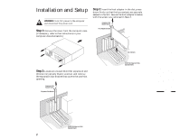
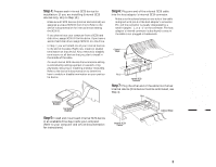
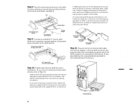
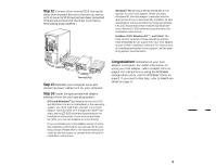
Installation and Setup WARNING: Turn OFF power to the computer and disconnect the power cord. Step 1: Remove the cover from the computer case. (If necessary, refer to the instructions in your computer documentation.) Step 3: Insert the host adapter in the slot; press down firmly so that the bus contacts are securely seated in the slot. Secure the host adapter bracket with the screw you removed in Step 2. Expansion Slot Bracket Screw Host Adapter Bracket Back of Your Computer Step 2: Locate an unused 16-bit ISA expansion slot (this slot is typically black); unscrew and remove the expansion slot bracket that covers the card-slot opening. Expansion Slot Bracket Screw Expansion Slot Bracket Bus Contacts 16-bit ISA Expansion Slots (typically black) AHA-1520B Installation Guide Part Number: 511162-00, Rev. A Page 2 of 16 Print Spec Number: 495339-00 Current Date: 5/30/96 Last Modified: May 30, 1996 3:43 pm File Location: n:\mario\1520b_ig.nec\1520b_ig.frm ECN Date: 6/11/95 AAAAAAAAAAAAAAAAAAAAAAAAAAAAAAAAAAAAAAAAAAAAAAAAAAAAAAAAAAAAAAAAAAAAAAAAAAAAAAAAAAAAAAAAAAAAAAAAAAAAAAAAAAAAAAAAAAAAAAAAAAAAAAAAAAAAAAAAAAAAAAAAAAAAAAAAAAAAAAAAAAAAAAAAAAAAAAAAAAAAAAAAAAAAAAAAAAAAAAAAAAAAAAAAAAAAAAAAAAAAAAAAAAAAAAAAAAAA 16-Bit ISA Expansion Slots (typically black) 2
-
 1
1 -
 2
2 -
 3
3 -
 4
4 -
 5
5 -
 6
6 -
 7
7 -
 8
8 -
9
-
10
-
11
-
12
-
13
-
14
-
15
-
16
 |
 |
