Adaptec 1520B User Guide - Page 3
Step 4, Step 5, Step 6, Step 7
 |
View all Adaptec 1520B manuals
Add to My Manuals
Save this manual to your list of manuals |
Page 3 highlights
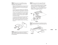
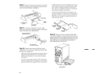
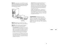
Step 4: Prepare each internal SCSI device for installation: (If you are installing External SCSI devices only, skip to Step 10.) s Make sure all SCSI devices (internal and external) are assigned a unique SCSI ID from 0 to 6. Refer to the device's documentation for instructions on setting the SCSI ID. If you plan to boot your computer from a SCSI hard disk drive, assign SCSI ID 0 to this drive. If you have a second hard disk drive, assign SCSI ID 1 to the drive. s In Step 7, you will attach one of your internal devices to the end of the cable. Right now, install (or enable) terminators on that device. Also, remove (or disable) terminators on all devices that you plan to install in the middle of the cable. On most internal SCSI devices the termination setting is controlled by setting a jumper or a switch, or by physically removing or installing a resistor module(s). Refer to the device's documentation to determine how to enable or disable termination on your particular device. Termination Enabled Termination Disabled Step 5: Install and mount each internal SCSI device in an available drive bay inside your computer. (Refer to your computer and device documentation for instructions.) Step 6: Plug one end of the internal SCSI cable into the host adapter's internal SCSI connector. s Make sure the colored stripe on one side of the cable is aligned with pin-1 of the host adapter's connector. Pin-1 of the connector is usually designated by a small triangle (v), or a "1" on the connector. The host adapter's internal connector is also keyed to ensure the cable is not plugged-in backwards. Colored Stripe 50-pin SCSI Ribbon Cable Pin 1 Internal SCSI Connector Step 7: Plug the other end of the cable into the last internal device (this device must be terminated, see Step 4). Pin 1 Internal SCSI Device Colored Stripe AHA-1520B Installation Guide Part Number: 511162-00, Rev. A Page 3 of 16 Print Spec Number: 495339-00 Current Date: 5/30/96 Last Modified: May 30, 1996 3:43 pm File Location: n:\mario\1520b_ig.nec\1520b_ig.frm ECN Date: 6/11/95 AAAAAAAAAAAAAAAAAAAAAAAAAAAAAAAAAAAAAAAAAAAAAAAAAAAAAAAAAAAAAAAAAAAAAAAAAAAAAAAAAAAAAAAAAAAAAAAAAAAAAAAAAAAAAAAAAAAAAAAAAAAAAAAAAAAAAAAAAAAAAAAAAAAAAAAAAAAAAAAAAAAAAAAAAAAAAAAAAAAAAAAAAAAAAAAAAAAAAAAAAAAAAAAAAAAAAAAAAAAAAAAAAAAAAAAAAAAA 3
-
 1
1 -
 2
2 -
 3
3 -
 4
4 -
 5
5 -
 6
6 -
 7
7 -
 8
8 -
 9
9 -
10
-
11
-
12
-
13
-
14
-
15
-
16
 |
 |
