Adaptec AHA-1540C Installation Guide - Page 2
Getting Started, Installing the Host Adapter, Connecting, Peripherals - aha 1542c user s manual
 |
View all Adaptec AHA-1540C manuals
Add to My Manuals
Save this manual to your list of manuals |
Page 2 highlights
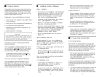
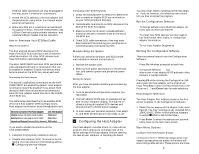
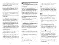
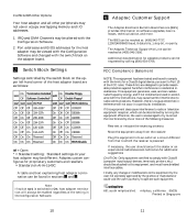
1 Getting Started This guide provides the steps required for basic installation of the AHA-1540C and AHA-1542C ISAto-SCSI Host Adapters. Procedures are the same for both adapters except when regarding the AHA1542C on-board floppy controller. Installation of your host adapter includes: 1. Installing the AHA (Adaptec Host Adapter) board in your computer 2. Installing your SCSI cable(s) and SCSI peripherals 3. Terminating the SCSI cabling bus 4. Adjusting your host adapter configuration set- tings if necessary 5. Loading software if necessary CAUTION Turn Off and disconnect power to the system and external equipment. Always refer to your personal computer's documentation for instructions on opening the system cover and adding option boards. You may not need to change your host adapter settings Your host adapter is already configured for the majority of ISA (AT compatible) or EISA class computers. Read sections 2 and 3 to determine whether you need to alter the adapter default settings. • A table identifying the adapter board switch block settings can be found in section 7 at the end of this Installation Guide. You may not need to load any software Your host adapter comes equipped with an onboard BIOS that allows you to use up to seven SCSI disk drives without additional software under MS®-DOS version 5.0 and above. Refer to section 5 for your specific software requirements. 1 2 Installing the Host Adapter Board Installation 1. Turn Off and disconnect power to the system and external equipment. Follow your ISA (or EISA) personal computer's instruction manual to remove the system cover and expose the expansion slots and external access covers. 2. Locate an unused expansion slot. Any standard ISA or EISA expansion slot will work. 3. Remove the corresponding expansion board access cover on the computer chassis. 4. Align and insert the ISA I/O bus connector on the bottom of the AHA-1540C/1542C into the chosen slot. Use the screw from the removed expansion slot cover to secure the AHA-1540C/1542C bracket to your ISA system chassis. 5. Do not replace the system cover or reconnect power yet! When to Set the Switches In most cases, you will never have to change the switch block settings. There are, however, certain options which do require adjustments to the switch block on the adapter board. The switch block is on the upper left-hand corner of the host adapter board. • A table identifying the switch block settings can be found in section 7 at the end of this Installation Guide. Here are some cases in which the switch block settings should be changed: Controlling Floppy Drives • If your floppy diskette drives are already running under another controller, disable the AHA-1542C floppy controller. • If you want to use the AHA-1542C floppy controller you must disable your existing one; refer to your computer or floppy controller user documentation. 2 • SW5 on the AHA-1540C must remain in the On/Closed position, even though there is no floppy controller on that host adapter. Multiple Host Adapters • Select a different I/O port address for each host adapter installed. You must know the port address of each installed host adapter in order to adjust it's settings with the Configuration Software. • Make sure that each host adapter is set to a separate BIOS address. Or, disable the BIOS on all but one of the host adapters. Not Controlling SCSI Disk Drives • If you do not want to use the host adapter to control hard disk drives, disabling the BIOS may save up to 60 seconds of boot-up time. This would be useful when running only SCSI tape or CD-ROMs, for example. 3 Connecting Peripherals Connecting Cables SCSI devices are cabled together in a single continuous daisy-chain of devices, called the SCSI bus. The bus may have no branches, but must run from device to device in a continuous series. The host adapter need not be at the end of the SCSI bus, unless only one other device is on the bus. • Only Single-Ended SCSI devices are supported by the AHA-1540C/1542C. Differential SCSI devices may be damaged if connected to the AHA-1540C/1542C bus. Consult your SCSI peripheral user documentation. If your system configuration includes both internal and external SCSI devices, the host adapter will be at the junction between the internal and external peripherals. 1. Lay out your cables and find the pin-1 element of each cable and peripheral connector. On internal cables, pin-1 is usually distinguished by a contrasting color on one edge of the ribbon cable. 3
-
 1
1 -
 2
2 -
 3
3 -
 4
4 -
 5
5
 |
 |
