Airlink AGSW1600V2 Quick Installation Guide - Page 5
Rear Panel, NOTICE, 2.3 LED indicators information
 |
View all Airlink AGSW1600V2 manuals
Add to My Manuals
Save this manual to your list of manuals |
Page 5 highlights
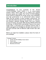
1.2.2 Rear Panel Figure 1-2 Rear Panel view of the Switch • AC Power Connector: Supports AC 100~240V, 50~60Hz. NOTICE: Do not cover or put anything on or surrounding the Switch while the Switch is operating. 1.2.3 LED indicators information The front panel LEDs provide instant status feedback and help monitoring and troubleshooting when needed. Figure 1-3 Front Panel view of the Switch 4
-
 1
1 -
 2
2 -
 3
3 -
 4
4 -
 5
5 -
 6
6 -
 7
7 -
 8
8 -
 9
9 -
 10
10 -
 11
11 -
12
-
13
 |
 |

4
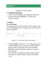
1.2.2 Rear Panel
Figure 1-2 Rear Panel view of the Switch
•
AC Power Connector: Supports AC 100~240V, 50~60Hz.
NOTICE:
Do not cover or put anything on or surrounding the Switch
while the Switch is operating.
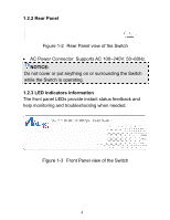
1.2.3 LED indicators information
The front panel LEDs provide instant status feedback and
help monitoring and troubleshooting when needed.
Figure 1-3 Front Panel view of the Switch