Alpine MRP-F240 User Manual
Alpine MRP-F240 Manual
 |
View all Alpine MRP-F240 manuals
Add to My Manuals
Save this manual to your list of manuals |
Alpine MRP-F240 manual content summary:
- Alpine MRP-F240 | User Manual - Page 1
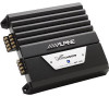
English Français Español R MRP-F240 4/3/2 CHANNEL POWER AMPLIFIER MRP-T220 2/1 CHANNEL POWER AMPLIFIER • OWNER'S MANUAL Please read this manual to maximize your enjoyment of the outstanding performance and feature capabilities of the equipment, then retain the manual for future reference. • MODE - Alpine MRP-F240 | User Manual - Page 2
- Alpine MRP-F240 | User Manual - Page 3
: Please read this OWNER'S MANUAL thoroughly to familiarize yourself with each control and function. We at ALPINE hope that your new MRP-F240/MRP-T220 will give you many years of listening enjoyment. In case of problems when installing your MRP-F240/ MRP-T220, please contact your authorized - Alpine MRP-F240 | User Manual - Page 4
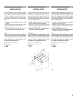
HALT USE IMMEDIATELY IF A PROBLEM APPEARS. Failure to do so may cause personal injury or damage to the product. Return it to your authorized Alpine dealer or the nearest Alpine Service Center for repairing. HAVE THE WIRING AND INSTALLATION DONE BY EXPERTS. The wiring and installation of this unit - Alpine MRP-F240 | User Manual - Page 5
amplifier should be mounted in a location which will allow for free circulation of air, such as inside the trunk. For alternate installation locations, please contact your authorized Alpine dealer. En raison de la sortie de puissance élevée du MRP-F240/ MRP ya instalado en la parte metálica del veh - Alpine MRP-F240 | User Manual - Page 6
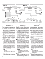
MRP-F240 English Français MRP-T220 Español SPEAKER OUTPUT BRIDGED CH-2 CH-1 CH-4 CH-3 25A BATTERY REMOTE GND FUSE POWER SUPPLY 20 25 - BRIDGED + - CH-2 + - CH-1 + SPEAKER OUTPUT 20A BATTERY REMOTE GND FUSE POWER SUPPLY (Left side/Côté gauche/Lado izquierdo) 17 1 16 15 14 - Alpine MRP-F240 | User Manual - Page 7
When not using the RCA Line Input connectors, you should connect these wires to the speaker output leads of your head unit. The MRP-F240/MRP-T220 accepts input from high power or standard power head units. NOTE: Use either RCA line level or speaker level inputs. Do not connect both at the same time - Alpine MRP-F240 | User Manual - Page 8
) the MRP-F240/MRP-T220. Therefore, the switch should be mounted so it is accessible to the driver. Make sure the switch is turned off when the vehicle is not running. Otherwise, the amplifier will remain on and drain the battery. 1 Blue/White 2 Power Antenna 3 Remote Turn-On Lead 4 To other Alpine - Alpine MRP-F240 | User Manual - Page 9
couvercle RCA fourni 2. • Método de fijación: Utilice los dos tornillos para metales incluidos 1 para montar la cubierta RCA incluida 2. RCA Terminal/Borne RCA/Terminal RCA (MRP-T220) 2 Fig. 4 1 9 - Alpine MRP-F240 | User Manual - Page 10
MRP-F240/MRP-T220 input gain knobs to the minimum (4V) position. Using a loud cassette or preferably a CD as a source, turn up the head unit volume until it distorts. Then, reduce the volume 1 step. You can then increase amplifier gain until the sound from the speakers entrada del MRPF240/MRP-T220 a - Alpine MRP-F240 | User Manual - Page 11
DEL SISTEMA • MRP-F240 (Left side/ Côté gauche/ Lado izquierdo) 28 R L -+ - + OFF HP LP (80Hz) FILTER OFF HP LP (80Hz) FILTER OFF HP LP (80Hz) FILTER Español 25 20 • MRP-T220 SPEAKER OUTPUT BRIDGED CH-2 CH-1 CH-4 CH-3 25A BATTERY REMOTE GND FUSE POWER SUPPLY -+ - + R L 27 - Alpine MRP-F240 | User Manual - Page 12
Connections/Connexions pontées/Conexiones derivadas • MRP-F240 L 29 -+ Français OFF HP LP (80Hz) FILTER SPEAKER OUTPUT BRIDGED CH-2 CH-1 CH-4 CH-3 (Left side/ Côté gauche/ Lado izquierdo) -+ R 29 25A BATTERY REMOTE GND FUSE POWER SUPPLY 53 • MRP-T220 CH-1+3 OFF HP LP PRE (80Hz - Alpine MRP-F240 | User Manual - Page 13
de entrada del altavoz • MRP-F240 Español • MRP-T220 NOM 0.5V NOM 0.5V +6dB MIN MAX GAIN OFF HP LP (80Hz) FILTER CH-1/2 MIN MAX 0dB +12dB GAIN BASS EQ CH-3/4 CH-1+3 OFF HP LP (80Hz) FILTER PRE OUT CH-2+4 CH-1 CH-3 CH-1 2 3 4 (L) INPUT (R) SPEAKER LEVEL INPUT CH-2 CH - Alpine MRP-F240 | User Manual - Page 14
PRE OUT CH-2+4 CH-1 CH-3 CH-1 2 3 4 R CH-2 (L) INPUT (R) CH-4 SPEAKER LEVEL INPUT (Right side/ Côté droit/ Lado derecho) OFF HP LP (80Hz) FILTER OFF HP LP (80Hz) FILTER 23 R L 31 Fig. 12 Español Important Tips on Bridging an Amplifier/Conseils importants lors de la mise en pont d'un - Alpine MRP-F240 | User Manual - Page 15
Hz to 20kHz) Per channel into 4 ohms (0.08% THD) ... MRP-F240: 40Wx4 MRP-T220: 50Wx2 Per channel into 2 ohms (0.3% THD) ..... MRP-F240: 50Wx4 MRP-T220: 70Wx2 Bridged into 4 ohms (0.3% THD) ......... MRP-F240: 100Wx2 MRP-T220: 140Wx1 Total MAX Power MRP-F240: 360W MRP-T220: 250W Frequency Response - Alpine MRP-F240 | User Manual - Page 16
device in accordance with the specifications in Subpart J of Part 15 of FCC Rules. This equipment generates and uses radio frequency energy, and it must be installed and used properly in accordance with the manufacturer's instructions. AVIS IMPORTANT Cet amplificateur a été testé et est conforme
-
 1
1 -
 2
2 -
 3
3 -
 4
4 -
 5
5 -
 6
6 -
 7
7 -
8
-
9
-
10
-
11
-
12
-
13
-
14
-
15
-
16
 |
 |

R
• OWNER'S MANUAL
Please read this manual to maximize your enjoyment of the outstanding
performance and feature capabilities of the equipment, then retain the
manual for future reference.
• MODE D'EMPLOI
Veuillez lire ce mode d'emploi pour tirer pleinement profit des
excellentes performances et fonctions de cet appareil, et conservez-le
pour toute référence future.
• MANUAL DE OPERACIÓN
Lea este manual, por favor, para disfrutar al máximo de las
excepcionales prestaciones y posibilidades funcionales que ofrece el
equipo, luego guarde el manual para usarlo como referencia en el futuro.
MRP-F240
4/3/2 CHANNEL POWER AMPLIFIER
MRP-T220
2/1 CHANNEL POWER AMPLIFIER
CONTENTS
WARNING
...............................................................
3
CAUTION
................................................................
4
INSTALLATION
.......................................................
5
CONNECTIONS
.......................................................
6
CONNECTIONS CHECK LIST
...................................
8
SWITCH SETTINGS
..............................................
10
SYSTEM DIAGRAMS
............................................
11
SPECIFICATIONS
..................................................
15
ACCESSORIES
•
RCA Cover
..........................................................
1
•
Machine Screw
...................................................
2
•
Self-Tapping Screw
............................................
4
•
Insulation Tube (for Power Supply/
for Speaker Output)
....................................
1 SET
•
Speaker Input Connector
....................................
1
TABLE DES MATIERES
AVERTISSEMENT
......................................................
3
ATTENTION
................................................................
4
INSTALLATION
..........................................................
5
CONNEXIONS
............................................................
6
LISTE DE VERIFICATION DES CONNEXIONS
.............
8
REGLAGES DE COMMUTATEUR
..............................
10
DIAGRAMMES DU SYSTEME
..................................
11
SPECIFICATIONS
.....................................................
15
ACCESSOIRES
•
Couvercle RCA
......................................................
1
•
Vis à métaux
..........................................................
2
•
Vis autotaraudeuse
................................................
4
•
Tube d’isolation (pour alimentation/
pour la sortie de haut-parleur)
.........................
1 JEU
•
Connecteur d’entrée de haut-parleur
..........................
1
ÍNDICE
ADVERTENCIA
........................................................
3
PRUDENCIA
...........................................................
4
INSTALACIÓN
.........................................................
5
CONEXIONES
.........................................................
6
LISTA DE VERIFICACIÓN DE CONEXIONES
............
8
AJUSTES DEL INTERRUPTOR
..............................
10
DIAGRAMAS DEL SISTEMA
.................................
11
ESPECIFICACIONES
.............................................
15
ACCESORIOS
•
Cubierta de RCA
.................................................
1
•
Tornillo para metales
..........................................
2
•
Tornillo autorroscante
........................................
4
•
Tubo de aislamiento (para la alimentación/
para la salida de altavoz)
........................
1 JUEGO
•
Conector de entrada del altavoz
.........................
1
Español
Français
English