Asus A7N8X-VM 400 A7N8X-VM/400 User's Manual
Asus A7N8X-VM 400 Manual
 |
View all Asus A7N8X-VM 400 manuals
Add to My Manuals
Save this manual to your list of manuals |
Asus A7N8X-VM 400 manual content summary:
- Asus A7N8X-VM 400 | A7N8X-VM/400 User's Manual - Page 1
Motherboard A7N8X-VM 400 User Manual - Asus A7N8X-VM 400 | A7N8X-VM/400 User's Manual - Page 2
written permission of ASUSTeK COMPUTER INC. ("ASUS"). Product warranty or service will not be extended if: (1) the product is repaired, modified the serial number of the product is defaced or missing. ASUS PROVIDES THIS MANUAL "AS IS" WITHOUT WARRANTY OF ANY KIND, EITHER EXPRESS OR IMPLIED, - Asus A7N8X-VM 400 | A7N8X-VM/400 User's Manual - Page 3
viii A7N8X-VM 400 specifications summary ix Chapter 1 - Motherboard Info 1-1 1.1 Welcome 1-2 1.2 Package contents 1-2 1.3 Special features 1-2 1.4 Motherboard components 1-3 1.5 Motherboard layout 1-6 1.6 Before you proceed 1-7 1.7 Central Processing Unit (CPU 1-7 1.8 System memory - Asus A7N8X-VM 400 | A7N8X-VM/400 User's Manual - Page 4
2-14 2.6 Boot Menu 2-15 2.6.1 Boot Settings Configuration 2-15 2.6.2 Security 2-17 2.7 Exit Menu 2-20 Chapter 3 - Software support 3-1 3.1 Installing an operating system 3-2 3.2 Support CD information 3-2 3.2.1 Running the support CD 3-2 3.2.3 Utilities menu 3-3 3.2.2 Drivers menu 3-3 iv - Asus A7N8X-VM 400 | A7N8X-VM/400 User's Manual - Page 5
. This equipment generates, uses and can radiate radio frequency energy and, if not installed and used in accordance with manufacturer's instructions, may cause harmful interference to radio communications. However, there is no guarantee that interference will not occur in a particular installation - Asus A7N8X-VM 400 | A7N8X-VM/400 User's Manual - Page 6
Contact a qualified service technician or your retailer. Operation safety • Before installing the motherboard and adding devices on it, carefully read all the manuals that came with . • If you encounter technical problems with the product, contact a qualified service technician or your retailer. vi - Asus A7N8X-VM 400 | A7N8X-VM/400 User's Manual - Page 7
used in this guide To make sure that you perform certain tasks properly, take note of the following symbols used throughout this manual. WARNING/DANGER information and for product and software updates. 1. ASUS Websites The ASUS websites worldwide provide updated information on ASUS hardware and - Asus A7N8X-VM 400 | A7N8X-VM/400 User's Manual - Page 8
Li-Te Road, Peitou, Taipei, Taiwan 112 Telephone +886-2-2894-3447 Web site www.asus.com.tw Technical Support Telephone(MB/Component) (Notebook) (Server/PC) (Networking) Support fax +886-2-2890-7121 (English) +886-2-2890-7122 (English) +886-2-2890-7123 (English) +886-2-2890-7902 (English) +886 - Asus A7N8X-VM 400 | A7N8X-VM/400 User's Manual - Page 9
A7N8X-VM 400 specifications summary CPU Chipset Front Side Bus (FSB) Memory Expansion slots IDE Graphics Audio LAN IEEE 1394 (optional) Hardware Monitoring Special Features Back Panel I/O Ports Internal I/O Connectors Socket A Type 462 for AMD Athlon™/Athlon™ XP CPUs 400/333/266 MHz FSB Support - Asus A7N8X-VM 400 | A7N8X-VM/400 User's Manual - Page 10
, AMI BIOS, ACPI 2.0, DMI, Green, PnP, TCAV, SMBIOS 2.3 PCI 2.2, USB 2.0/1.1 DMI 2.0, WOL, WOR, WO_USB, WO_KB/MS, SM Bus Device drivers ASUS PC Probe ASUS Update ASUS Screen Saver Adobe Acrobat Reader Trend Microtm PC-cillin anti-virus software User Guide ASUS A7N8X-VM 400 series support CD 40-pin - Asus A7N8X-VM 400 | A7N8X-VM/400 User's Manual - Page 11
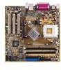
Chapter 1 This chapter describes the features of the A7N8X-VM 400 motherboard. It includes brief descriptions of the motherboard components, and illustrations of the layout, jumper settings, and connectors. Product introduction - Asus A7N8X-VM 400 | A7N8X-VM/400 User's Manual - Page 12
. ASUS A7N8X-VM 400 motherboard Micro-ATX form factor: 9.6 in x 9.6 in ASUS A7N8X-VM 400 series support CD 40-pin 80-conductor ribbon cable for UltraATA 133/100/66/33 IDE drives Ribbon cable for a 3.5-inch floppy drive Bag of extra jumper caps I/O shield User's Manual 1.3 Special features Latest - Asus A7N8X-VM 400 | A7N8X-VM/400 User's Manual - Page 13
motherboard, learn about its major components and available features to facilitate the installation and future upgrades. Refer to the succeeding pages for the component descriptions. 12 34 5 67 16 15 14 13 12 11 10 9 8 17 18 19 20 21 22 26 25 24 23 ASUS A7N8X-VM 400 Motherboard - Asus A7N8X-VM 400 | A7N8X-VM/400 User's Manual - Page 14
+5V standby lead (+5VSB). 3 CPU Socket. Socket 462 (Socket A) Zero Insertion Force (ZIF) socket for the AMD Athlon™/AMD Athlon XP™ processors. 4 NorthBridge Controller. The NVIDIA® nForce2™ IGP North Bridge controller chipset. The controller supports a 64/128bit DDR memory controller and up to 2 GB - Asus A7N8X-VM 400 | A7N8X-VM/400 User's Manual - Page 15
USB devices such as a mouse and PDA. 24 VGA port. This 15-pin VGA port connects to a VGA monitor. 25 Serial port. This port connects to your serial mouse and other serial devices. 26 PS/2 keyboard port. This purple 6-pin connector is for a PS/2 keyboard. ASUS A7N8X-VM 400 Motherboard 1-5 - Asus A7N8X-VM 400 | A7N8X-VM/400 User's Manual - Page 16
FLOPPY1 24.5cm (9.6in) 1.5 Motherboard layout PS/2 T: Mouse B: Keyboard 24.5cm (9.6in) Socket :Mic In Realtek RTL8201 AUX1 CD1 U46 nVidia nForce2 IGP CHA_FAN A7N8X-VM Accelerated Graphics Port (AGP8X1) PCI 1 FPAUDIO Audio Codec PCI 2 SPDIF1 PCI 3 BUZZER1 23 45 Super I/O CR2032 - Asus A7N8X-VM 400 | A7N8X-VM/400 User's Manual - Page 17
components. 1.7 Central Processing Unit (CPU) The motherboard provides a Socket A (462) for CPU installation. AMD processors offer gigahertz speeds to support all the latest computing platforms and applications. The A7N8X-VM 400 supports AMD Athlon™/AMD Athlon™ XP processors with "QuantiSpeed" data - Asus A7N8X-VM 400 | A7N8X-VM/400 User's Manual - Page 18
1.8 System memory The motherboard has two Double Data Rate (DDR) DIMM sockets that supports up to 2GB non-ECC PC2700/2100 DDR DIMMs. A7N8X-VM 400 104 Pins 80 Pins A7N8X-VM 400 184-Pin DDR DIMM Sockets A DDR DIMM is keyed with a notch so that it fits in only one direction. DO NOT force a DIMM into - Asus A7N8X-VM 400 | A7N8X-VM/400 User's Manual - Page 19
ATA Controller *These IRQs are usually available for ISA or PCI devices. IRQ assignments for this motherboard AB C D E F G PCI slot 1 used - - - - - - PCI slot 2 -- - used - - - PCI slot 3 -- used - - - - AGP slot - used - - - - - ASUS A7N8X-VM 400 Motherboard 1-9 - Asus A7N8X-VM 400 | A7N8X-VM/400 User's Manual - Page 20
they fit the AGP slot on your motherboard. A7N8X-VM 400 AGP Card without Retention Notch A7N8X-VM 400 Accelerated Graphics Port (AGP8X) 1.9.4 PCI slots Three 32-bit PCI slots are available on this motherboard. The slots support PCI cards such as LAN card, SCSI card, USB card, and other cards that - Asus A7N8X-VM 400 | A7N8X-VM/400 User's Manual - Page 21
must NOT exceed the power supply capability (+5VSB) whether under normal condition or in sleep mode. USBPW34 12 23 A7N8X-VM 400 A7N8X-VM 400 USB Device Wake Up +5V (Default) +5VSB USBPW12 12 23 +5V (Default) +5VSB USBPW56 12 23 +5V (Default) +5VSB ASUS A7N8X-VM 400 Motherboard 1-11 - Asus A7N8X-VM 400 | A7N8X-VM/400 User's Manual - Page 22
, [1-2]. 4. Re-install the battery. 5. Plug the power cord and turn ON the computer. 6. Hold down the key during the boot process and enter BIOS setup to re-enter data. A7N8X-VM 400 CLRTC1 12 23 Normal (Default) A7N8X-VM 400 Clear RTC RAM Clear CMOS 1-12 Chapter 1: Product Information - Asus A7N8X-VM 400 | A7N8X-VM/400 User's Manual - Page 23
to the hard disk documentation for the jumper settings. BIOS supports specific device bootup. If you have more than two A7N8X-VM 400 NOTE: Orient the red markings (usually zigzag) on the IDE ribbon cable to PIN 1. SEC_IDE PRI_IDE A7N8X-VM 400 IDE Connectors PIN 1 ASUS A7N8X-VM 400 Motherboard - Asus A7N8X-VM 400 | A7N8X-VM/400 User's Manual - Page 24
pin FLOPPY1) This connector supports the provided floppy drive ribbon cable. After connecting one end to the motherboard, connect the other end to the floppy drive. (Pin 5 is removed to prevent incorrect insertion when using ribbon cables with pin 5 plug.) FLOPPY1 A7N8X-VM 400 NOTE: Orient the red - Asus A7N8X-VM 400 | A7N8X-VM/400 User's Manual - Page 25
GAME/MIDI port on the module connects a joystick or a game pad for playing games, and MIDI devices for playing or editing audio files. +5V J1B2 J1CY GND GND J1CX J1B1 +5V A7N8X-VM 400 A7N8X-VM 400 Game Connector GAME1 MIDI_IN J2B2 J2CY MIDI_OUT J2CX J2B1 +5V ASUS A7N8X-VM 400 Motherboard 1-15 - Asus A7N8X-VM 400 | A7N8X-VM/400 User's Manual - Page 26
connectors support cooling fans of 350mA~740mA (8.88W max.) or a total of 1A~2.22A (26.64W max.) at +12V. Connect the fan cables to the fan connectors on the motherboard, making sure that the black wire of each cable matches the ground pin of the connector. CPU_FAN1 Rotation +12V GND A7N8X-VM 400 - Asus A7N8X-VM 400 | A7N8X-VM/400 User's Manual - Page 27
out_L A7N8X-VM 400 Front Panel Audio Connector 9. OnBoard LED The green Light Emitting Diode (LED) lights-ON if there is standby power and lights-OFF when the power is turned off. SB_PWR1 A7N8X-VM 400 ON Standby Power A7N8X-VM 400 Onboard LED OFF Powered Off ASUS A7N8X-VM 400 Motherboard - Asus A7N8X-VM 400 | A7N8X-VM/400 User's Manual - Page 28
allow you to receive stereo audio input from sound sources such as a CD-ROM, TV tuner, MPEG card or modem. A7N8X-VM 400 AUX1 (White) CD1 (Black) Left Audio Channel Ground Right Audio Channel A7N8X-VM 400 Internal Audio Connectors 11. Digital Audio Connector (6-1 pin SPDIF1) This connector - Asus A7N8X-VM 400 | A7N8X-VM/400 User's Manual - Page 29
pin connector connects to the front panel daughter card with the audio tv-out port. A7N8X-VM 400 TV_OUT 1 A7N8X-VM 400 TV Out Connector 13. Serial Port 2 connector (10-1 pin back of the system chassis. A7N8X-VM 400 COM2 PIN 1 A7N8X-VM 400 Serial COM2 Bracket ASUS A7N8X-VM 400 Motherboard 1-19 - Asus A7N8X-VM 400 | A7N8X-VM/400 User's Manual - Page 30
Speaker +5V IDELED ExtSMI# Ground PWR Ground Reset Ground A7N8X-VM 400 A7N8X-VM 400 System Panel Connectors IDE LED SMI Lead Reset SW ATX Power the system between ON and SLEEP, or ON and SOFT OFF, depending on the BIOS or OS settings. Pressing the power switch while in the ON mode for more than - Asus A7N8X-VM 400 | A7N8X-VM/400 User's Manual - Page 31
Chapter 2 This chapter tells how to change system settings through the BIOS Setup Menus. Detailed descriptions of the BIOS parameters are also provided. BIOS information - Asus A7N8X-VM 400 | A7N8X-VM/400 User's Manual - Page 32
while updating the BIOS. This may cause boot problems. Just repeat the process, and if the problem persists, load the original BIOS file you saved to the boot disk. If the Flash Memory Writer utility is not able to successfully update a complete BIOS file, call the ASUS service center for support - Asus A7N8X-VM 400 | A7N8X-VM/400 User's Manual - Page 33
BIOS Setup program so that the computer can recognize these changes and record them in the CMOS RAM of the EEPROM. The EEPROM on the motherboard predetermined choices. Because the BIOS software is constantly being updated, the following BIOS setup screens and descriptions A7N8X-VM 400 Motherboard 2-3 - Asus A7N8X-VM 400 | A7N8X-VM/400 User's Manual - Page 34
field Resets the current screen to its Setup Defaults Saves changes and exits Setup General help In addition to the Item Specific Help window, the BIOS setup program also provides a General Help screen. You may launch this screen from any menu by simply pressing or the + combination - Asus A7N8X-VM 400 | A7N8X-VM/400 User's Manual - Page 35
Setup program, note that explanations appear in the Item Specific Help window located to the right of each menu. This window displays the help text for the currently highlighted field. 2.3 Main > + keys to move between the hour, minute, and second fields. ASUS A7N8X-VM 400 Motherboard 2-5 - Asus A7N8X-VM 400 | A7N8X-VM/400 User's Manual - Page 36
20.0GB LBA Mode : Supported Block Mode : 16 Sectors PIO Mode : Supported Ultra DMA : Ultra DMA-5 SMART Monitoring: Supported Type LBA/Large Mode Block mode. Select [Auto] to enable LBA mode if the device supports it and the device is not already formatted with LBA Mode disabled. [Disabled - Asus A7N8X-VM 400 | A7N8X-VM/400 User's Manual - Page 37
supports it memory. The values for these fields are automatically detected. Refer to the screen capture below for details. AMI BIOS Version : 08.00.08 Build Data : 08/04/03 Processor Type Speed Count : AMD DURON(TM) : 1600MHz : 1 System Memory Size : 256MB ASUS A7N8X-VM 400 Motherboard - Asus A7N8X-VM 400 | A7N8X-VM/400 User's Manual - Page 38
Chipset Configuration Video Frame Buffer Size Graphics Aperture Size MDA Access Control Primary Video OnBoard TV-out Format [64MB] [64MB] [PCI] [PCI] [PAL] Video Frame Buffer Size [ 64MB] This field sets the size of the video frame buffer. The settings on this field is valid only for motherboard - Asus A7N8X-VM 400 | A7N8X-VM/400 User's Manual - Page 39
in case of multiple video controllers. Configuration options Super IO Chipset Onboard CODEC Interface Audio CODEC Interface Onboard LAN Interface Onboard LAN Boot ROM BIOS to select the Parallel Port Base Address. Configuration options: [Disabled] [378] [278] [3BC] ASUS A7N8X-VM 400 Motherboard 2-9 - Asus A7N8X-VM 400 | A7N8X-VM/400 User's Manual - Page 40
[DMA1] [DMA3] Parallel Port IRQ [IRQ7] This field allows the BIOS to select the Parallel Port IRQ. Configuration options: [IRQ5l] [IRQ7] Audio CODEC Interface [Auto] This field allows you to disable or set to automatic the AUDIO CODEC interface. Configuration options: [Disabled] [Auto] Onboard LAN - Asus A7N8X-VM 400 | A7N8X-VM/400 User's Manual - Page 41
Channel 1 DMA Channel 3 DMA Channel 5 DMA Channel 7 Reserved Memory Size [Available] [Available] [Available] [Available] [Available] [ configures the Plug and Play O/S feature. If set to [No] the BIOS configures all the devices attached to the system. If set to [Yes], A7N8X-VM 400 Motherboard 2-11 - Asus A7N8X-VM 400 | A7N8X-VM/400 User's Manual - Page 42
Size [Disabled] This field specifies the reserved memory block for use of legacy ISA devices. Configuration options: [Disabled] [16k] [32k] [64k] 2.5 Power Menu The Power menu allows you to reduce power consumption. This feature turns off the video display and shuts down the hard disk after a period - Asus A7N8X-VM 400 | A7N8X-VM/400 User's Manual - Page 43
Restore On AC/Power Loss Resume on Keyboard Resume on PS/2 Mouse PME Resume Ring In Resume OnBoard LAN Resume RTC Resume [Last State] [Disabled] [Disabled] [Disabled] [Disabled] [Disabled] [Disabled] the +5VSB lead. Configuration options: [Disabled] [Enabled] ASUS A7N8X-VM 400 Motherboard 2-13 - Asus A7N8X-VM 400 | A7N8X-VM/400 User's Manual - Page 44
onboard LAN to generate the motherboard, CPU, and power temperatures CPU Fan motherboard, that field shows 0RPM. VCORE Voltage, 3.3V Voltage, 5V Voltage, 12V Voltage The onboard hardware monitor automatically detects the voltage output through the onboard voltage regulators. 2-14 Chapter 2: BIOS - Asus A7N8X-VM 400 | A7N8X-VM/400 User's Manual - Page 45
Configuration fields include FLOPPY DRIVE, IDE Hard Drive, ATAPI CD-ROM, and Other Boot Device. 2.6.1 Boot Settings Lock PS/2 Mouse Support Wait for 'F1' If Error Hit 'DEL' Message Display Interrupt 19 Capture [Enabled] [Enabled] [Force BIOS] [On] [ Enabled] ASUS A7N8X-VM 400 Motherboard 2-15 - Asus A7N8X-VM 400 | A7N8X-VM/400 User's Manual - Page 46
mode for option ROM. Configuration options: [Force BIOS] [Keep Current] Bootup Num-Lock [On] This field selects the power-on state for the NumLock key. Configuration options: [Off] [On] PS/2 Mouse Support [Auto] This sets the PS/2 mouse support. Configuration options: [Disabled] [Auto] Wait for 'F1 - Asus A7N8X-VM 400 | A7N8X-VM/400 User's Manual - Page 47
. A pop-up window will appear; Type in a RAM, unplug the all the power cables and remove the button cell battery. Re-install the battery after about 2 seconds, then power up the system. Refer to section "Managing and updating your BIOS" on how to update the BIOS. ASUS A7N8X-VM 400 Motherboard - Asus A7N8X-VM 400 | A7N8X-VM/400 User's Manual - Page 48
press Enter. The message "Password Uninstalled" appears. If you forget your BIOS password, you can clear clear it by erasing the CMOS Real Time Clock (RTC) RAM. See section "2.7 Jumpers" for information on how to erase the RTC RAM. After you have set a supervisor password, the other items appear to - Asus A7N8X-VM 400 | A7N8X-VM/400 User's Manual - Page 49
BIOS checks for user password both when accessing Setup and booting the system. Configuration options: [Setup] [Always] Boot Sector Virus Protection [Disabled] Allows you to enable or disable the boot sector virus protection. Configuration options: [Disabled] [Enabled] ASUS A7N8X-VM 400 Motherboard - Asus A7N8X-VM 400 | A7N8X-VM/400 User's Manual - Page 50
. The CMOS RAM is sustained by an onboard backup battery and stays on even when the PC is turned off. When you select this option, a confirmation window appears. Select [Yes] to save changes and system date, system time, and password, the BIOS asks for a confirmation before exiting. 2-20 Chapter - Asus A7N8X-VM 400 | A7N8X-VM/400 User's Manual - Page 51
for each of the parameters on the Setup menus. When you select this option or if you press , a confirmation window appears. Select [Yes] to load default values. Select Exit Saving Changes or make other changes before saving the values to the non-volatile RAM. ASUS A7N8X-VM 400 Motherboard 2-21 - Asus A7N8X-VM 400 | A7N8X-VM/400 User's Manual - Page 52
2-22 Chapter 2: BIOS information - Asus A7N8X-VM 400 | A7N8X-VM/400 User's Manual - Page 53
Chapter 3 This chapter describes the contents of the support CD that comes with the motherboard package. Software support - Asus A7N8X-VM 400 | A7N8X-VM/400 User's Manual - Page 54
system This motherboard supports Windows 98SE/ME/2000/XP as well as Linux Red Hat, SuSE, TurboLinux and Caldera operating systems (OS). Always install the latest OS version and corresponding updates so you can maximize the features of your hardware. Because motherboard settings and hardware - Asus A7N8X-VM 400 | A7N8X-VM/400 User's Manual - Page 55
fan rotations, CPU temperature, and system voltages, and alerts you on any detected problems. This utility helps you keep your computer at a healthy operating condition. Using ASUS PC Probe Monitoring Monitor Summary Shows a summary of the items being monitored. ASUS A7N8X-VM 400 motherboard 3-3 - Asus A7N8X-VM 400 | A7N8X-VM/400 User's Manual - Page 56
times of the PC's temperature, fan rotation, and voltages. CPU Cooling System Setup Lets you select when to enable software CPU cooling. When When CPU Overheated is selected, the CPU cooling system is enabled whenever the CPU temperature reaches the threshold value. 3-4 Chapter 3: Software support - Asus A7N8X-VM 400 | A7N8X-VM/400 User's Manual - Page 57
on the current CPU temperature and predefined threshold. Hard Drives Shows the used and free space of the PC's hard disk drives and the file allocation table or file system used. Information Memory Shows the PC memory load, memory usage, and paging file usage. ASUS A7N8X-VM 400 motherboard 3-5 - Asus A7N8X-VM 400 | A7N8X-VM/400 User's Manual - Page 58
information pertinent to the PC, such as CPU type, CPU speed, and internal/external frequencies, and memory size. Utility Lets you run programs outside and pause or resume all system monitoring. When the ASUS PC Probe senses a problem with your PC, portions of the ASUS PC Probe icon change to red, - Asus A7N8X-VM 400 | A7N8X-VM/400 User's Manual - Page 59
the ASUS FTP site nearest you to avoid network traffic, or choose Auto Select. Click Next. 4. From the FTP site, select the BIOS version that you wish to download. Click Next. 5. Follow the instructions on the succeeding screens to complete the update process. ASUS A7N8X-VM 400 motherboard 3-7 - Asus A7N8X-VM 400 | A7N8X-VM/400 User's Manual - Page 60
If you selected the option to update the BIOS from a file, a window pops up prompting you to locate the file. Select the file, click Save, then follow the screen instructions to complete the update process. 3-8 Chapter 3: Software support
-
 1
1 -
 2
2 -
 3
3 -
 4
4 -
 5
5 -
 6
6 -
 7
7 -
8
-
9
-
10
-
11
-
12
-
13
-
14
-
15
-
16
-
17
-
18
-
19
-
20
-
21
-
22
-
23
-
24
-
25
-
26
-
27
-
28
-
29
-
30
-
31
-
32
-
33
-
34
-
35
-
36
-
37
-
38
-
39
-
40
-
41
-
42
-
43
-
44
-
45
-
46
-
47
-
48
-
49
-
50
-
51
-
52
-
53
-
54
-
55
-
56
-
57
-
58
-
59
-
60
 |
 |

Motherboard
A7N8X-VM 400
User Manual