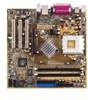
Asus A7N8X-VM 400 A7N8X-VM/400 User's Manual - Page 29
ASUS A7N8X-VM 400 Motherboard, Serial Port 2 connector 10-1 pin COM2, TV out connector 6-1 pin U46
 |
View all Asus A7N8X-VM 400 manuals
Add to My Manuals
Save this manual to your list of manuals |
Page 29 highlights
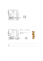
12. TV out connector (6-1 pin U46) This 6-1 pin connector connects to the front panel daughter card with the audio tv-out port. A7N8X-VM 400 TV_OUT 1 A7N8X-VM 400 TV Out Connector 13. Serial Port 2 connector (10-1 pin COM2) This connector accommodates a second serial port using an optional serial port bracket. Connect the bracket cable to this connector then install the bracket into a slot opening at the back of the system chassis. A7N8X-VM 400 COM2 PIN 1 A7N8X-VM 400 Serial COM2 Bracket ASUS A7N8X-VM 400 Motherboard 1-19
-
 1
1 -
2
-
3
-
4
-
5
-
6
-
7
-
8
-
9
-
10
-
11
-
12
-
13
-
14
-
15
-
16
-
17
-
18
-
19
-
20
-
21
-
22
-
23
-
 24
24 -
 25
25 -
 26
26 -
 27
27 -
 28
28 -
 29
29 -
 30
30 -
 31
31 -
 32
32 -
 33
33 -
 34
34 -
35
-
36
-
37
-
38
-
39
-
40
-
41
-
42
-
43
-
44
-
45
-
46
-
47
-
48
-
49
-
50
-
51
-
52
-
53
-
54
-
55
-
56
-
57
-
58
-
59
-
60
 |
 |

ASUS A7N8X-VM 400 Motherboard
1-19
13. Serial Port 2 connector (10-1 pin COM2)
This connector accommodates a second serial port using an optional serial
port bracket. Connect the bracket cable to this connector then install the
bracket into a slot opening at the back of the system chassis.
12. TV out connector (6-1 pin U46)
This 6-1 pin connector connects to the front panel daughter card with the audio
tv-out port.
A7N8X-VM 400
A7N8X-VM 400 TV Out Connector
1
TV_OUT
A7N8X-VM 400
A7N8X-VM 400 Serial COM2 Bracket
PIN 1
COM2