Asus A8N-SLI A8N-SLI English edition user's manual, version E2024
Asus A8N-SLI - Motherboard - ATX Manual
 |
UPC - 610839124862
View all Asus A8N-SLI manuals
Add to My Manuals
Save this manual to your list of manuals |
Asus A8N-SLI manual content summary:
- Asus A8N-SLI | A8N-SLI English edition user's manual, version E2024 - Page 1
A8N-SLI Motherboard - Asus A8N-SLI | A8N-SLI English edition user's manual, version E2024 - Page 2
Product warranty or service will not be extended if: (1) the product is repaired, modified or altered, unless such repair, modification of alteration is authorized in writing by ASUS; or (2) the serial number of the product is defaced or missing. ASUS PROVIDES THIS MANUAL "AS IS" WITHOUT WARRANTY - Asus A8N-SLI | A8N-SLI English edition user's manual, version E2024 - Page 3
A8N-SLI specifications summary vii Chapter 1: Hardware information 1.1 Before you proceed 1-2 1.2 Motherboard overview 1-3 1.2.1 Placement direction 1-3 1.2.2 Screw holes 1-3 1.2.3 Motherboard layout 1-4 1.2.4 Layout contents 1-5 1.3 Central Processing Unit (CPU 1-7 1.3.1 Installing the CPU - Asus A8N-SLI | A8N-SLI English edition user's manual, version E2024 - Page 4
Contents Chapter 2: BIOS setup 2.1 Managing and updating your BIOS 2-2 2.1.1 Creating a bootable floppy disk 2-2 2.1.2 AwardBIOS Flash Utility 2-3 2.1.3 ASUS CrashFree BIOS 2 utility 2-7 2.2 BIOS Setup program 2-8 2.2.1 BIOS menu bar 2-9 2.2.2 Legend bar 2-9 2.3 Main Menu 2-11 2.3.1 System - Asus A8N-SLI | A8N-SLI English edition user's manual, version E2024 - Page 5
. This equipment generates, uses and can radiate radio frequency energy and, if not installed and used in accordance with manufacturer's instructions, may cause harmful interference to radio communications. However, there is no guarantee that interference will not occur in a particular installation - Asus A8N-SLI | A8N-SLI English edition user's manual, version E2024 - Page 6
Contact a qualified service technician or your retailer. Operation safety • Before installing the motherboard and adding devices on it, carefully read all the manuals that came with . • If you encounter technical problems with the product, contact a qualified service technician or your retailer. vi - Asus A8N-SLI | A8N-SLI English edition user's manual, version E2024 - Page 7
A8N-SLI specifications summary CPU Chipset Front Side Bus Memory Expansion slots Storage Audio LAN IEEE 1394 USB BIOS features Special features Socket 939 for AMD Athlon™ 64FX/AMD Athlon™ 64 processor Supports AMD 64 architecture that enables simultaneous 32-bit and 64-bit architecture NVIDIA® - Asus A8N-SLI | A8N-SLI English edition user's manual, version E2024 - Page 8
x Optical S/PDIF Out port 1 x PS/2 keyboard port 8-Channel audio ports 1 x Floppy disk drive connector 2 x IDE connectors 4 x Serial ATA connectors 1 x CPU fan connector 2 x Chassis fan connectors 1 x Chipset fan connector 3 x USB connectors 1 x IEEE 1394a connector 1 x Serial port connector 1 x 24 - Asus A8N-SLI | A8N-SLI English edition user's manual, version E2024 - Page 9
This chapter lists the hardware setup procedures that you have to perform when installing system components. It includes description of the jumpers and connectors on the motherboard. Hardware information - Asus A8N-SLI | A8N-SLI English edition user's manual, version E2024 - Page 10
before removing or plugging in any motherboard component. The red warning LED lights up when you installed two graphics cards but did not connect the ASUS EZ Plug™. The illustration below shows the location of the onboard LEDs. SLI_WARN_LED A8N-SLI ® A8N-SLI Onboard LED ON When use 2 Graphics - Asus A8N-SLI | A8N-SLI English edition user's manual, version E2024 - Page 11
chassis as indicated in the image below. 1.2.2 Screw holes Place nine screws into the holes indicated by circles to secure the motherboard to the chassis. Do not overtighten the screws! Doing so can damage the motherboard. Place this side towards the rear of the chassis A8N-SLI ASUS A8N-SLI 1-3 - Asus A8N-SLI | A8N-SLI English edition user's manual, version E2024 - Page 12
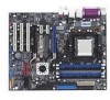
EATXPWR FLOPPY SEC_IDE PRI_IDE 30.5cm (12.0in) 1.2.3 Motherboard layout 24.5cm (9.6in) PS/2KBMS T: Mouse B: WARN_LED CD AUX Marvell 88E1111 EZ_PLUG PCIEX16_1 PCIEX1_1 A8N-SLI SLI_CON PCIEX1_2 PCIEX16_2 ® PCI1 nVidia CK804 SLI CHIP_FAN 1394 Controller IE_1394_2 PCI2 PCI3 SB_PWR CR2032 - Asus A8N-SLI | A8N-SLI English edition user's manual, version E2024 - Page 13
Subwoofer port 10. USB 2.0 ports 3 and 4 11. USB 2.0 ports 1 and 2 12. IEEE 1394a port 13. Optical S/PDIF Out port 14. Coaxial S/PDIF Out port 15. PS/2 keyboard port Page 1-12 1-16 1-16 1-16 Page 1-17 Page 1-18 1-18 1-18 1-18 1-18 1-18 1-18 1-19 1-19 1-19 1-19 1-19 1-19 1-19 1-19 ASUS A8N-SLI 1-5 - Asus A8N-SLI | A8N-SLI English edition user's manual, version E2024 - Page 14
) 4. Serial ATA connectors (7-pin SATA1, SATA2, SATA3, SATA4) 5. CPU fan connector (3-pin CPU_FAN) 6. Chassis fan connectors (3-pin CHA1_FAN, CHA2_FAN) 7. Chipset fan connector (3-pin CHIP_FAN) 8. Power fan connector (3-pin PWR_FAN) 9. USB connectors (10-1 pin USB78, USB56, USB910) 10. IEEE 1394a - Asus A8N-SLI | A8N-SLI English edition user's manual, version E2024 - Page 15
note of the marked corner (with gold triangle) on the CPU. This mark should match a specific corner on the socket to ensure correct installation. Gold triangle 1.3.1 Installing the CPU To install a CPU: 1. Locate the CPU socket on the motherboard. A8N-SLI ® A8N-SLI CPU Socket 939 ASUS A8N-SLI 1-7 - Asus A8N-SLI | A8N-SLI English edition user's manual, version E2024 - Page 16
90°-100° angle. Socket lever Make sure that the socket lever is lifted up to 90°-100° angle; otherwise the CPU does not fit in completely. 3. Position the CPU above the socket such that the CPU corner with the gold triangle matches the socket corner with a small triangle. 4. Carefully insert the - Asus A8N-SLI | A8N-SLI English edition user's manual, version E2024 - Page 17
base Retention bracket Retention bracket lock Your boxed CPU heatsink and fan assembly should come with installation instructions for the CPU, heatsink, and the retention mechanism. If the instructions in this section do not match the CPU documentation, follow the latter. ASUS A8N-SLI 1-9 - Asus A8N-SLI | A8N-SLI English edition user's manual, version E2024 - Page 18
near the retention bracket lock) to the retention module base. A clicking sound denotes that the retention bracket is in place. Make sure that the fan and heatsink assembly perfectly fits the retention mechanism module base; otherwise, you cannot snap the retention bracket in place. 4. Push down the - Asus A8N-SLI | A8N-SLI English edition user's manual, version E2024 - Page 19
the fan and heatsink assembly is in place, connect the CPU fan cable to the connector on the motherboard labeled CPU_FAN. CPU_FAN A8N-SLI ® A8N-SLI CPU fan connector Do not forget to connect the CPU fan connector! Hardware monitoring errors can occur if you fail to plug this connector. ASUS A8N-SLI - Asus A8N-SLI | A8N-SLI English edition user's manual, version E2024 - Page 20
for the latest qualified vendors list (QVL). • Due to chipset resource allocation, the system may detect less than 4 GB of system memory when you installed four 1 GB DDR memory modules. • Due to CPU limitation, this motherboard does not support DIMM modules with 128 Mb memory chips or double-sided - Asus A8N-SLI | A8N-SLI English edition user's manual, version E2024 - Page 21
to do so may cause severe damage to both the motherboard and the components. 1. Unlock a DIMM socket by Support the DIMM lightly with your fingers when pressing the retaining clips. The DIMM might get damaged when it flips out with extra force. 2. Remove the DIMM from the socket. ASUS A8N-SLI - Asus A8N-SLI | A8N-SLI English edition user's manual, version E2024 - Page 22
the expansion cards that they support. Make sure to unplug the physical injury and damage motherboard components. 1.5.1 Installing Remove the system unit cover (if your motherboard is already installed in a chassis). 3. the necessary BIOS settings, if any. See Chapter 2 for information on BIOS setup. - Asus A8N-SLI | A8N-SLI English edition user's manual, version E2024 - Page 23
- Onboard 1394a shared - - -- - - - When using PCI cards on shared slots, ensure that the drivers support "Share IRQ" or that the cards do not need IRQ assignments; otherwise, conflicts will arise between the two PCI groups, making the system unstable and the card inoperable. ASUS A8N-SLI 1-15 - Asus A8N-SLI | A8N-SLI English edition user's manual, version E2024 - Page 24
shows a graphics card installed on the PCI Express x16 slot. This motherboard does not support the Scalable Link Interface™ (SLI) mode for two identical SLI™-ready PCI Express x16 graphics cards. Single card mode (default) supports: - 1 x PCI Express™ x16 graphics card on either blue or black slot - Asus A8N-SLI | A8N-SLI English edition user's manual, version E2024 - Page 25
boot failure! A8N-SLI ® A8N-SLI Clear RTC RAM CLRTC 12 23 Normal (Default) Clear CMOS You do not need to clear the RTC when the system hangs due to overclocking. For system failure due to overclocking, use the C.P.R. (CPU Parameter Recall) feature. Shut down and reboot the system so the BIOS - Asus A8N-SLI | A8N-SLI English edition user's manual, version E2024 - Page 26
devices. 3 . L A N 2 ( R J - 4 5 ) p o r t . Supported by the Marvell® 88E81111 Gigabit LAN controller, this port allows Gigabit connection to a Local Area Network (LAN i g h t b l u e ) . This port connects the tape, CD, DVD player, or other audio sources. 7 . L i n e O u t p o r t ( l i m e ) . - Asus A8N-SLI | A8N-SLI English edition user's manual, version E2024 - Page 27
an external audio output device via an optical S/PDIF cable. 1 4 . C o a x i a l S / P D I F O u t p o r t . This port connects an external audio output device via a coaxial S/PDIF cable. 1 5 . P S / 2 k e y b o a r d p o r t ( p u r p l e ) . This port is for a PS/2 keyboard. ASUS A8N-SLI 1-19 - Asus A8N-SLI | A8N-SLI English edition user's manual, version E2024 - Page 28
is removed to prevent incorrect cable connection when using an FDD cable with a covered Pin 5. A8N-SLI ® FLOPPY NOTE: Orient the red markings on the floppy ribbon cable to PIN 1. PIN 1 A8N-SLI Floppy disk drive connector 2 . Serial port connector (10-1 pin COM1) This connector is for a serial - Asus A8N-SLI | A8N-SLI English edition user's manual, version E2024 - Page 29
cable has three connectors: a blue connector for the primary IDE connector on the motherboard, a black connector for an Ultra DMA 133/100/66 IDE slave device (optical for UltraDMA133/100/66 IDE devices. SEC_IDE PRI_IDE A8N-SLI ® A8N-SLI IDE connectors PIN 1 NOTE: Orient the red markings (usually zigzag - Asus A8N-SLI | A8N-SLI English edition user's manual, version E2024 - Page 30
Supported by the NVIDIA® nForce™4 SLI chipset Serial ATA boot or data hard BIOS. See section "2.4.3 Onboard Devices Configuration" on pages 2-24 and 2-26 for details. GND RSATA_RXN4 RSATA_RXP4 GND RSATA_TXN4 RSATA_TXP4 GND GND RSATA_RXN3 RSATA_RXP3 GND RSATA_TXN3 RSATA_TXP3 GND A8N-SLI ® A8N-SLI - Asus A8N-SLI | A8N-SLI English edition user's manual, version E2024 - Page 31
, and chipset fan connectors (3-pin CPU_FAN, 3-pin CHA1_FAN, 3-pin CHA2_FAN, 3-pin PWR_FAN, 3-pin CHIP_FAN)) These fan connectors support cooling fans of 350 mA ~ 2000 mA (24 W max.) or a total of 1 A ~ 3.48 A (41.76 W max.) at +12 V. Connect the fan cable to the fan connector on the motherboard - Asus A8N-SLI | A8N-SLI English edition user's manual, version E2024 - Page 32
NC USB+5V USB_P6USB_P6+ GND NC USB+5V USB_P8USB_P8+ GND NC USB+5V USB_P9USB_P9+ GND A8N-SLI USB 2.0 connectors USB+5V USB_P7USB_P7+ GND USB78 1 USB56 1 USB910 1 USB+5V USB_P5USB_P5+ GND Never connect a 1 3 9 4 c a b l e to the USB connectors. Doing so will damage the motherboard! 7 . IEEE - Asus A8N-SLI | A8N-SLI English edition user's manual, version E2024 - Page 33
the system will not boot. • Use of unstable or may not boot up if the CPU type PCIe™ x16 graphics PCIe™ x 1 card PCI cards IEEE 1394 devices USB devices Required +12V current Required wattage Heavy Athlon 64 FX +12V DC GND A8N-SLI EZ_PLUG +5V ® EZ_DET GND +12V A8N-SLI ATX power connectors - Asus A8N-SLI | A8N-SLI English edition user's manual, version E2024 - Page 34
Ground Ground Left Audio Channel Left Audio Channel Ground Ground Right Audio Channel A8N-SLI Internal audio connectors 10. Front panel audio connector (10-1 pin FP_AUDIO) This connector is for a chassis-mounted front panel audio I/O module that supports legacy AC '97 audio standard. Connect one - Asus A8N-SLI | A8N-SLI English edition user's manual, version E2024 - Page 35
labeled "Chassis Signal" and "Ground" are shorted with a jumper cap. Remove the jumper caps only when you intend to use the chassis intrusion detection feature. A8N-SLI ® CHASSIS (Default) A8N-SLI Chassis alarm lead +5VSB_MB Chassis Signal GND ASUS A8N-SLI 1-27 - Asus A8N-SLI | A8N-SLI English edition user's manual, version E2024 - Page 36
supports several chassis-mounted functions. PLED PWRSW PLED+ PLEDPWR GND A8N-SLI F_PANEL IDE_LED+ IDE_LED- Ground Reset NC ® IDE_LED RESET * Requires an ATX power supply. A8N-SLI system in SLEEP or SOFT-OFF mode depending on the BIOS settings. Pressing the power switch for more than four - Asus A8N-SLI | A8N-SLI English edition user's manual, version E2024 - Page 37
This chapter tells how to change the system settings through the BIOS Setup menus. Detailed descriptions of the BIOS parameters are also provided. 2 BIOS setup ASUS A8N-SLI 2-1 - Asus A8N-SLI | A8N-SLI English edition user's manual, version E2024 - Page 38
BIOS file for this motherboard using the ASUS Update utility. 2.1.1 Creating a bootable floppy disk 1. Do either one of the following to create a bootable floppy disk. DOS environment a. Insert a 1.44 MB floppy disk into the drive. b. At the DOS prompt, type format A:/S then press . Windows - Asus A8N-SLI | A8N-SLI English edition user's manual, version E2024 - Page 39
save it to the bootable floppy disk you created earlier. 2. Copy the AwardBIOS Flash Utility (awdflash.exe) from the Software folder of the support CD to the floppy disk with the latest BIOS file. 3. Boot the system in DOS mode using the bootable floppy disk you created earlier. ASUS A8N-SLI 2-3 - Asus A8N-SLI | A8N-SLI English edition user's manual, version E2024 - Page 40
Utility. 5. At the prompt, type a w d f l a s h then press AwardBIOS Flash Utility for ASUS V1.09 (C) Phoenix Technologies Ltd. All Rights Reserved . The Award For NF-KC804-A8N-SLI-00 DATE: 11/30/2004 BIOS Flash Utility screen Flash Type - SST 49LF004A/B /3.3V appears. File Name to - Asus A8N-SLI | A8N-SLI English edition user's manual, version E2024 - Page 41
Flash Type - SST 49LF004A/B /3.3V flashed the BIOS file. File Name to Program: 1001-001.bin Remove the floppy disk then press to Flashing Complete Press to Continue restart the system. 111222333 Write OK 111222333 No Update 111222333 Write Fail F1 Reset ASUS A8N-SLI 2-5 - Asus A8N-SLI | A8N-SLI English edition user's manual, version E2024 - Page 42
: old.bin Message: Please Wait! 4. The utility saves the current BIOS file to the floppy disk, then returns to the BIOS flashing process. AwardBIOS Flash Utility for ASUS V1.09 (C) Phoenix Technologies Ltd. All Rights Reserved For NF-KC804-A8N-SLI-00 DATE: 11/30/2004 Flash Type - SST 49LF004A - Asus A8N-SLI | A8N-SLI English edition user's manual, version E2024 - Page 43
BIOS recovery... Checking for floppy... Floppy found! Reading file "A8N-SLI.ROM". Completed. Start flashing... DO NOT shut down or reset the system while updating the BIOS! Doing so can cause system boot failure! 4. Restart the system after the utility completes the updating process. ASUS A8N-SLI - Asus A8N-SLI | A8N-SLI English edition user's manual, version E2024 - Page 44
Setup program This motherboard supports a programmable Flash ROM that you can update using the provided utility described in section "2.1 Managing and updating your BIOS." Use the BIOS Setup program when you are installing a motherboard, reconfiguring your system, or prompted to "Run Setup." This - Asus A8N-SLI | A8N-SLI English edition user's manual, version E2024 - Page 45
this menu to configure and enable Power Management features. BOOT Use this menu to configure the default system device used F5> Function Description Displays the General Help screen from anywhere in the BIOS Setup Jumps to the Exit menu or returns to the main menu from a sub ASUS A8N-SLI 2-9 - Asus A8N-SLI | A8N-SLI English edition user's manual, version E2024 - Page 46
General help In addition to the Item Specific Help window, the BIOS setup program also provides a General Help screen. > to display the first page, press to go to the last page. To exit the help window, press or . Sub-menu Note that a right pointer symbol (as shown on the left - Asus A8N-SLI | A8N-SLI English edition user's manual, version E2024 - Page 47
Fourth SATA Master Installed Memory 17:8:12 Thu, Mar 17 2005 [1.44M, 3.5 in.] [ST320410A] [ASUS CD--S520/] [None] [None] [None] [None] [None] [None] 256MB Select Menu Item automatically displays the amount of conventional memory detected by the system during the boot process. ASUS A8N-SLI 2-11 - Asus A8N-SLI | A8N-SLI English edition user's manual, version E2024 - Page 48
for the remaining fields on this sub-menu. If the hard disk was already formatted on a previous system, the setup BIOS may detect incorrect parameters. Select [Manual] to manually enter the IDE hard disk drive parameters. If no drive is installed select [None]. Configuration options: [None] [Auto - Asus A8N-SLI | A8N-SLI English edition user's manual, version E2024 - Page 49
disk drive information into BIOS, use a disk utility, such as FDISK, to partition and format new IDE hard disk drives. This is necessary so that you can write or read data from the hard disk. Make sure to set the partition of the Primary IDE hard disk drives to active. ASUS A8N-SLI 2-13 - Asus A8N-SLI | A8N-SLI English edition user's manual, version E2024 - Page 50
0 Head 0 Precomp 0 Landing Zone 0 Sector 0 Select Menu Item Specific Help Sets the type of fixed disk connected to the system. The BIOS automatically detects the values opposite the dimmed items (Capacity, Cylinder, Head, Precomp, Landing Zone and Sector). These values are not user - Asus A8N-SLI | A8N-SLI English edition user's manual, version E2024 - Page 51
of sectors per track. This item is not configurable. After entering the IDE hard disk drive information into BIOS, use a disk utility, such as FDISK, to partition and format new IDE hard disk drives. This is to active. 2.3.7 Installed Memory Shows the size of installed memory. ASUS A8N-SLI 2-15 - Asus A8N-SLI | A8N-SLI English edition user's manual, version E2024 - Page 52
other system devices. Take caution when changing the settings of the Advanced menu items. Incorrect field values may cause the system to malfunction. CPU Configuration Chipset PCIPnP Onboard Device Configuration SLI Configuration Select Menu Item Specific Help Press Enter to set. 2-16 Chapter - Asus A8N-SLI | A8N-SLI English edition user's manual, version E2024 - Page 53
2200MHz Cache RAM 512K AMD K8 Cool 'n' Quiet control [Enabled] Select Menu Item Specific Help Enable/Disable Cool`n'Quiet function. AMD K8 Cool 'n' Quiet control [Enabled] Enables or disables the AMD K8 Cool `n' Quiet™ feature. Configuration options: [Enabled] ~ [Disabled] ASUS A8N-SLI 2-17 - Asus A8N-SLI | A8N-SLI English edition user's manual, version E2024 - Page 54
the configuration options. Chipset DRAM Configuration Errata 94 menu show the DRAM-related information that the BIOS auto-detects. DRAM Configuration Timing Mode x Memclock x Row precharge time (Trp) x 1/T/2T Memory Timing Bottom of 32-bit [31:24] IO DRAM Over 4G Remapping MTRR mapping mode [ - Asus A8N-SLI | A8N-SLI English edition user's manual, version E2024 - Page 55
to [Manual] Bottom of 32-bit [31:24] IO [E0] Allows you to se the minumum and maximum limits of the 32-bit memory-mapped IO location. DRAM Over 4G Remapping [Disabled] Enables or disables DRAM remapping when using 4 GB of system memory. Configuration options: [Disabled] [Enabled] ASUS A8N-SLI 2-19 - Asus A8N-SLI | A8N-SLI English edition user's manual, version E2024 - Page 56
Configuration options: [PCI slot] [PCIEx] Resources Controlled By [Auto When set to [Auto(ESCD)], this allows the BIOS to automatically configure all the boot and Plug and Play devices. When set to [Manual], you can assign the available IRQ resources to the PCI devices. Configuration options: [Auto - Asus A8N-SLI | A8N-SLI English edition user's manual, version E2024 - Page 57
e s C o n t r o l l e d B y item is set to Manual. IRQ Resources IRQ-3 assigned to IRQ-4 assigned to IRQ-5 assigned to IRQ-7 assigned to IRQ-9 problem. If you are using standard VGA cards, leave this field to the default setting [Disabled]. Configuration options: [Disabled] [Enabled] ASUS A8N-SLI - Asus A8N-SLI | A8N-SLI English edition user's manual, version E2024 - Page 58
> to display a pop-up menu with the configuration options. Onboard Device Configuration IDE Function Setup NVRAID Configuration USB Configuration Onboard LAN Onboard LAN Boot ROM AC97 Audio PCI IEEE 1394a Serial Port 1 Address Parallel Port Address Parallel Port Mode ECP Mode Use DMA [Enabled - Asus A8N-SLI | A8N-SLI English edition user's manual, version E2024 - Page 59
ATA 1 port. Configuration options: [Disabled] [Enabled] SATA DMA transfer [Enabled] Allows you to enable or disable the SATA DMA transfer access. Configuration options: [Disabled] [Enabled] ASUS A8N-SLI 2-23 - Asus A8N-SLI | A8N-SLI English edition user's manual, version E2024 - Page 60
Master/Slave RAID [Disabled] Enables or disables the RAID function of the primary or secondary master or slave IDE. Configuration options: [Enabled] [Disabled] 2-24 Chapter 2: BIOS setup - Asus A8N-SLI | A8N-SLI English edition user's manual, version E2024 - Page 61
[Enabled] Allows you to enable or disable the USB 2.0 controller. Configuration options: [Disabled] [Enabled] USB Legacy Support [Enabled] Allows you to enable or disable support for USB devices on legacy operating systems (OS). Configuration options: [Disabled] [Enabled] ASUS A8N-SLI 2-25 - Asus A8N-SLI | A8N-SLI English edition user's manual, version E2024 - Page 62
installed a PCI LAN card. Configuration options: [Disabled] [Enabled] Onboard LAN Boot ROM [Disabled] Setting to [Enabled] allowed the BIOS to invoke the boot ROM of the onboard LAN chip. Configuration options: [Enabled] [Disabled] AC97 Audio [Enabled] Allows you to enable or disable the onboard AC - Asus A8N-SLI | A8N-SLI English edition user's manual, version E2024 - Page 63
SLI configuration SLI Configuration EZ-Plug Warning [Enabled] Select Menu Item Specific Help EZ-Plug Warning [Enabled] Allows you to enable or disable the EZ-Plug warning feature. Configuration options: [Disabled] [Enabled] ASUS A8N-SLI 2-27 - Asus A8N-SLI | A8N-SLI English edition user's manual, version E2024 - Page 64
to enable or disable the Advanced Configuration and Power Interface (ACPI) support in the Advanced Programmable Interrupt Controller (APIC). When set to Enabled, the ACPI APIC table pointer is included in the RSDT pointer list. Configuration options: [Disabled] [Enabled] 2-28 Chapter 2: BIOS setup - Asus A8N-SLI | A8N-SLI English edition user's manual, version E2024 - Page 65
the Wake-On-Ring feature. This feature requires an ATX power supply that provides at least 1A on the +5VSB lead. Configuration options: [Disabled] [Enabled] ASUS A8N-SLI 2-29 - Asus A8N-SLI | A8N-SLI English edition user's manual, version E2024 - Page 66
on the system. This feature requires an ATX power supply that provides at least 1A on the +5VSB lead. Configuration options: [Disabled] [Enabled] 2-30 Chapter 2: BIOS setup - Asus A8N-SLI | A8N-SLI English edition user's manual, version E2024 - Page 67
. CPU Fan Speed/CHA1 Fan Speed The onboard hardware monitor automatically detects and displays the Chassis, CPU, and Chip fan speeds in rotations per minute (RPM). If the fan is not connected to the motherboard, the field shows 0. These items are not user-configurable. ASUS A8N-SLI 2-31 - Asus A8N-SLI | A8N-SLI English edition user's manual, version E2024 - Page 68
the value you set, the CPU fan runs at full speed. Configuration options: [51ºC] [54ºC] [57ºC] [60ºC] [63ºC] [66ºC] [69ºC] [72ºC] [75ºC] [78ºC] [81ºC] This item becomes configurable only when the Q - F a n C o n t r o l l e r item is set to [Enabled]. 2.6 Boot Menu This Boot menu items allow you to - Asus A8N-SLI | A8N-SLI English edition user's manual, version E2024 - Page 69
Hard Disk] [Disabled] Select Menu Item Specific Help Select your boot device priority. 1st ~ xth Boot Device These items specify the boot device priority sequence from the available devices. The number of devices , or to move it down the list. Press to exit this menu. ASUS A8N-SLI 2-33 - Asus A8N-SLI | A8N-SLI English edition user's manual, version E2024 - Page 70
Enabled] Setting to [Enabled] allows the system to skip certain tests while booting, decreasing the time needed to boot the system. Configuration options: [Disabled] [Enabled] Boot Up Floppy Seek [Enabled] When [Enabled], the BIOS will seek the floppy disk drive to determine whether the drive has 40 - Asus A8N-SLI | A8N-SLI English edition user's manual, version E2024 - Page 71
you to enable or disable the full screen logo display feature. Configuration options: [Disabled] [Enabled] Set this item to [Enabled] to use the ASUS MyLogo™ feature. Halt On [No Errors] Sets the system to halt on errors according to the system functions specified in each option. Configuration - Asus A8N-SLI | A8N-SLI English edition user's manual, version E2024 - Page 72
DISABLED!!! Press any key to continue..." 2. Press any key to return to the menu. A note about passwords The Supervisor password is required to enter the BIOS Setup program preventing unauthorized access. The User password is required to boot the system preventing unauthorized use. 2-36 Chapter - Asus A8N-SLI | A8N-SLI English edition user's manual, version E2024 - Page 73
instructions. Password Check [Setup] This field requires you to enter the password before entering the BIOS window appears (with a blinking [Y]): • press to save and exit • type [N], then press , or simply press , to cancel the command and return to the Exit menu ASUS A8N-SLI - Asus A8N-SLI | A8N-SLI English edition user's manual, version E2024 - Page 74
to fields other than system date, system time, and password, the BIOS asks for a confirmation before exiting. Load Setup Defaults This option allows . When you select this option or if you press , a confirmation window appears. Select [Yes] to load default values. Select Exit Saving Changes or
-
 1
1 -
 2
2 -
 3
3 -
 4
4 -
 5
5 -
 6
6 -
 7
7 -
8
-
9
-
10
-
11
-
12
-
13
-
14
-
15
-
16
-
17
-
18
-
19
-
20
-
21
-
22
-
23
-
24
-
25
-
26
-
27
-
28
-
29
-
30
-
31
-
32
-
33
-
34
-
35
-
36
-
37
-
38
-
39
-
40
-
41
-
42
-
43
-
44
-
45
-
46
-
47
-
48
-
49
-
50
-
51
-
52
-
53
-
54
-
55
-
56
-
57
-
58
-
59
-
60
-
61
-
62
-
63
-
64
-
65
-
66
-
67
-
68
-
69
-
70
-
71
-
72
-
73
-
74
 |
 |

Motherboard
A8N-SLI