Asus AT5NM10T-I NA User Manual - Page 24
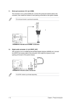
AT5NM10T-I LVDS connector
 |
View all Asus AT5NM10T-I NA manuals
Add to My Manuals
Save this manual to your list of manuals |
Page 24 highlights
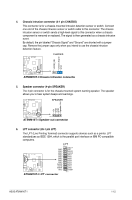
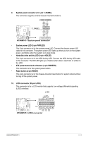
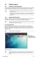
PLED+ PLEDPWR GND HD_LED+ HD_LED- Ground Reset AT5NM10T-I 9. System panel connector (10-1 pin F_PANEL) This connector supports several chassis-mounted functions. PLED PWRBTN F_PANEL PIN 1 +HDLED RESET AT5NM10T-I System panel connector • System power LED (2-pin PWRLED) This 2-pin connector is for the system power LED. Connect the chassis power LED cable to this connector. The system power LED lights up when you turn on the system power, and blinks when the system is in sleep mode. • Hard disk drive activity LED (2-pin +HDLED) This 2-pin connector is for the HDD Activity LED. Connect the HDD Activity LED cable to this connector. The HD LED lights up or flashes when data is read from or written to the HDD. • ATX power button/soft-off button (2-pin PWRBTN) This connector is for the system power button. • Reset button (2-pin RESET) This 2-pin connector is for the chassis-mounted reset button for system reboot without turning off the system power. 10. LVDS connector (30-pin LVDS) This connector is for a LCD monitor that supports Low-voltage differential signaling (LVDS) interface. LVDS PIN 1 AT5NM10T-I LVDS connector GND VCC VCC GND VEEDID LCD_PID0 LCD_PID1 LDDC_CS# DDC DATA DDC CLK VLED VLED VLED VLED VLED_GND BLIM BL_ON GND DATA_0DATA_0+ GDN DATA_1DATA_1+ GND DATA_2DATA_2+ GND CLKCLK+ GND AT5NM10T-I ASUS AT5NM10T-I 1-14
-
 1
1 -
2
-
3
-
4
-
5
-
6
-
7
-
8
-
9
-
10
-
11
-
12
-
13
-
14
-
15
-
16
-
17
-
18
-
 19
19 -
 20
20 -
 21
21 -
 22
22 -
 23
23 -
 24
24 -
 25
25 -
 26
26 -
 27
27 -
 28
28 -
 29
29 -
30
-
31
-
32
-
33
-
34
-
35
-
36
-
37
-
38
-
39
-
40
-
41
-
42
 |
 |
