Asus AT5NM10T-I NA User Manual - Page 25
AT5NM10T-I Serial port COM2 connector
 |
View all Asus AT5NM10T-I NA manuals
Add to My Manuals
Save this manual to your list of manuals |
Page 25 highlights
AT5NM10T-I 11. Serial port connector (10-1 pin COM2) The connector is for a serial (COM) port. Connect the serial port module cable to the connector, then install the module to a slot opening at the back of the system chassis. The serial port bracket is purchased separately. COM2 PIN 1 AT5NM10T-I Serial port (COM2) connector 12. Digital audio connector (4-1 pin SPDIF_OUT) This connector is for an additional Sony/Philips Digital Interface (S/PDIF) port. Connect the S/PDIF Out module cable to this connector, then install the module to a slot opening at the back of the system chassis. AT5NM10T-I Digital audio connector The S/PDIF module is purchased separately. AT5NM10T-I +5V SPDIFOUT GND 1-15 Chapter 1: Product introduction
-
 1
1 -
2
-
3
-
4
-
5
-
6
-
7
-
8
-
9
-
10
-
11
-
12
-
13
-
14
-
15
-
16
-
17
-
18
-
19
-
 20
20 -
 21
21 -
 22
22 -
 23
23 -
 24
24 -
 25
25 -
 26
26 -
 27
27 -
 28
28 -
 29
29 -
 30
30 -
31
-
32
-
33
-
34
-
35
-
36
-
37
-
38
-
39
-
40
-
41
-
42
 |
 |

1-15
Chapter 1: Product introduction
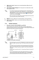
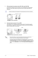
11.
Serial port connector (10-1 pin COM2)
The connector is for a serial (COM) port. Connect the serial port module cable to the
connector, then install the module to a slot opening at the back of the system chassis.
The serial port bracket is purchased separately.
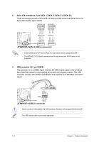
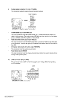
12.
Digital audio connector (4-1 pin SPDIF_OUT)
This connector is for an additional Sony/Philips Digital Interface (S/PDIF) port. Connect
the S/PDIF Out module cable to this connector, then install the module to a slot
opening at the back of the system chassis.
The S/PDIF module is purchased separately.
AT5NM10T-I
AT5NM10T-I Serial port (COM2) connector
PIN 1
COM2
AT5NM10T-I
AT5NM10T-I Digital audio connector
+5V
SPDIFOUT
GND