Asus M2N-VM DVI User Manual - Page 25
System memory
 |
View all Asus M2N-VM DVI manuals
Add to My Manuals
Save this manual to your list of manuals |
Page 25 highlights
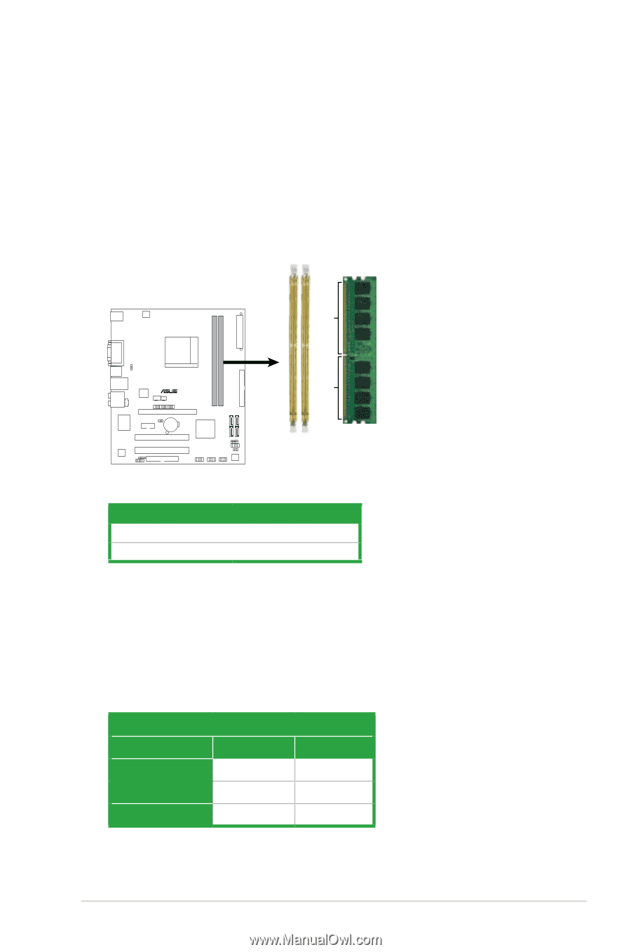
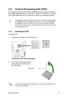
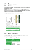
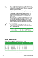
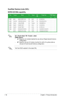
1.7 System memory 1.7.1 Overview The motherboard comes with two Double Data Rate 2 (DDR2) Dual Inline Memory Modules (DIMM) sockets. A DDR2 module has the same physical dimensions as a DDR DIMM but has a 240-pin footprint compared to the 184-pin DDR DIMM. DDR2 DIMMs are notched differently to prevent installation on a DDR DIMM socket. The figure illustrates the location of the DDR2 DIMM sockets: 128 Pins 112 Pins R M2N-CM DVI DIMM_A1 DIMM_B1 M2N-CM DVI 240-pin DDR2 DIMM Sockets Channel Channel A Channel B Sockets DIMM_A1 DIMM_B1 1.7.2 Memory configurations You may install 256 MB, 512 MB, 1 GB, and 2 GB unbuffered ECC / non-ECC DDR2 DIMMs into the DIMM sockets. Recommended memory configurations Mode Single-Channel Dual-channel Sockets DIMM_A1 - Populated Populated DIMM_B1 Populated - Populated ASUS M2N-CM DVI 1-13
-
 1
1 -
2
-
3
-
4
-
5
-
6
-
7
-
8
-
9
-
10
-
11
-
12
-
13
-
14
-
15
-
16
-
17
-
18
-
19
-
 20
20 -
 21
21 -
 22
22 -
 23
23 -
 24
24 -
 25
25 -
 26
26 -
 27
27 -
 28
28 -
 29
29 -
 30
30 -
31
-
32
-
33
-
34
-
35
-
36
-
37
-
38
-
39
-
40
-
41
-
42
-
43
-
44
-
45
-
46
-
47
-
48
-
49
-
50
-
51
-
52
-
53
-
54
-
55
-
56
-
57
-
58
-
59
-
60
-
61
-
62
-
63
-
64
-
65
-
66
-
67
-
68
-
69
-
70
-
71
-
72
-
73
-
74
-
75
-
76
-
77
-
78
-
79
-
80
-
81
-
82
-
83
-
84
-
85
-
86
-
87
-
88
-
89
-
90
-
91
-
92
-
93
-
94
-
95
-
96
-
97
 |
 |