Asus M2N68-AM SE User Manual - Page 20
M2N68-AM SE IDE connector
 |
View all Asus M2N68-AM SE manuals
Add to My Manuals
Save this manual to your list of manuals |
Page 20 highlights
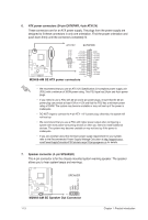
2. IDE connector (40-1 pin PRI_IDE) The onboard IDE connector is for an Ultra DMA 133/100/66 signal cable. There are three connectors on each Ultra DMA 133 / 100 / 66 signal cable: blue, black, and gray. Connect the blue connector to the motherboard's IDE connector, then select one of the following modes to configure your devices. Single device Two devices Drive jumper setting Cable-Select or Master Cable-Select Master Slave Mode of device(s) - Master Slave Master Slave Cable connector Black Black Gray Black or gray Pin 20 on the IDE connector is removed to match the covered hole on the Ultra DMA cable connector. This prevents incorrect insertion when you connect the IDE cable. • If any device jumper is set as "Cable-Select", ensure that all other device jumpers have the same setting. • Use the 80-conductor IDE cable for Ultra DMA 133/100/66 IDE devices. PRI_IDE PIN1 M2N68-AM SE NOTE:Orient the red markings on the IDE ribbon cable to PIN 1. M2N68-AM SE IDE connector 3. Optical drive audio in connector (4-pin CD) This connector allows you to receive stereo audio input from sound sources such as a CD-ROM, TV tuner, or MPEG card. CD Right Audio Channel Left Audio Channel GND GND M2N68-AM SE M2N68-AM SE Internal audio connector 1-11 Chapter 1: Product introduction
-
 1
1 -
2
-
3
-
4
-
5
-
6
-
7
-
8
-
9
-
10
-
11
-
12
-
13
-
14
-
 15
15 -
 16
16 -
 17
17 -
 18
18 -
 19
19 -
 20
20 -
 21
21 -
 22
22 -
 23
23 -
 24
24 -
 25
25 -
26
-
27
-
28
-
29
-
30
-
31
-
32
-
33
-
34
-
35
-
36
-
37
-
38
-
39
-
40
-
41
-
42
-
43
-
44
-
45
-
46
-
47
-
48
 |
 |
