Asus M5A78L-M LE USB3 User Guide
Asus M5A78L-M LE USB3 Manual
 |
View all Asus M5A78L-M LE USB3 manuals
Add to My Manuals
Save this manual to your list of manuals |
Asus M5A78L-M LE USB3 manual content summary:
- Asus M5A78L-M LE USB3 | User Guide - Page 1
Motherboard M5A78L-M LE/USB3 - Asus M5A78L-M LE USB3 | User Guide - Page 2
the express written permission of ASUSTeK COMPUTER INC. ("ASUS"). Product warranty or service ASUS. ASUS ASSUMES NO RESPONSIBILITY OR LIABILITY FOR ANY ERRORS OR INACCURACIES THAT MAY APPEAR IN THIS MANUAL licenses. If however you encounter any problems in obtaining the full corresponding source code - Asus M5A78L-M LE USB3 | User Guide - Page 3
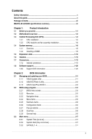
information...v About this guide...v Package contents...vii M5A78L-M LE/USB3 specifications summary vii Chapter 1: Product introduction 1.1 Before you proceed 1-1 1.2 Motherboard overview 1-2 1.3 Central Processing Unit (CPU 1-4 1.3.1 CPU installation 1-5 1.3.2 CPU heatsink and fan - Asus M5A78L-M LE USB3 | User Guide - Page 4
JumperFree Configuration 2-9 2.4.2 CPU Configuration 2-12 2.4.3 Chipset 2-13 2.4.4 Onboard Devices Configuration 2-14 2.4.5 PCIPnP 2-15 2.4.6 USB Configuration 2-15 2.5 Power menu 2-16 2.5.1 Suspend Mode [Auto 2-16 2.5.2 ACPI 2.0 Support [Enabled 2-16 2.5.3 ACPI APIC Support [Enabled 2-16 - Asus M5A78L-M LE USB3 | User Guide - Page 5
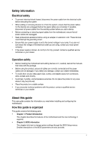
. • If you encounter technical problems with the product, contact a qualified service technician or your retailer. About this guide This user guide contains the information you need when installing and configuring the motherboard. How this guide is organized This guide contains the following parts - Asus M5A78L-M LE USB3 | User Guide - Page 6
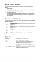
updates. 1. ASUS websites The ASUS website provides updated information on ASUS hardware and software products. Refer to the ASUS contact Conventions used in this guide To ensure that you perform certain tasks properly, take note of the following symbols used throughout this manual. DANGER/WARNING: - Asus M5A78L-M LE USB3 | User Guide - Page 7
motherboard 2 x Serial ATA 3.0 Gb/s cables 1 x I/O Shield Support DVD User Guide If any of the above items is damaged or missing, contact your retailer. M5A78L-M LE/USB3 specifications summary CPU Chipset Front side bus Memory Expansion slots Storage / RAID LAN Audio AMD® Socket AM3+ for AMD® FX - Asus M5A78L-M LE USB3 | User Guide - Page 8
M5A78L-M LE/USB3 specifications summary USB ASUS Unique Features Back panel I/O ports Internal I/O connectors BIOS Support DVD Form factor 8*USB 2.0 ports (4 at mid-board, 4 at back panel) 2*USB 3.0 ports (2 at back panel) ASUS EPU - EPU Core Unlocker ASUS Exclusive Features - Anti-Surge - ASUS - Asus M5A78L-M LE USB3 | User Guide - Page 9
Before you proceed Take note of the following precautions before you install motherboard components or change any motherboard settings. • Unplug the power cord from the wall socket before to do so may cause severe damage to the motherboard, peripherals, or components. ASUS M5A78L-M LE/USB3 1-1 - Asus M5A78L-M LE USB3 | User Guide - Page 10
in the image. 1.2.2 Screw holes Place six screws into the holes indicated by circles to secure the motherboard to the chassis. Do not overtighten the screws! Doing so can damage the motherboard. Place this side towards the rear of the chassis M5A78L-M LE/USB3 1-2 Chapter 1: Product introduction - Asus M5A78L-M LE USB3 | User Guide - Page 11
1042A LAN_USB12 CHA_FAN ICS 9LPRS483 AUDIO PCIEX1_1 AMD® 760G Realtek 8111GR Super I/O ALC 887-VD2 AAFP PCIEX16 16Mb M5A78L-M LE/USB3 BIOS BATTERY AMD® SB710 SPEAKER 5 PCI1 F_PANEL 6 CLRTC USB78 USB56 SATA3G_1 SATA3G_2 SATA3G_3 SATA3G_4 10 9 8 7 ASUS M5A78L-M LE/USB3 1-3 - Asus M5A78L-M LE USB3 | User Guide - Page 12
(10-1 pin USB56, USB78) 9. Clear RTC RAM (2-pin CLRTC) 10. Front panel audio connector (10-1 pin AAFP) Page 1-16 1-15 1-4 1-8 1-17 1-18 1-17 1-19 1-12 1-19 1.3 Central Processing Unit (CPU) The motherboard comes with an AM3+ socket designed for AMD® FX™ Series/Phenom™ II/ Athlon™ II/Sempron™ 100 - Asus M5A78L-M LE USB3 | User Guide - Page 13
1.3.1 CPU installation 1 2 3 4 ASUS M5A78L-M LE/USB3 1-5 - Asus M5A78L-M LE USB3 | User Guide - Page 14
1.3.2 CPU heatsink and fan assembly installation Apply the Thermal Interface Material to the CPU heatsink and CPU before you install the heatsink and fan if necessary. To install the CPU heatsink and fan assembly 1 2 3 4 5 1-6 Chapter 1: Product introduction - Asus M5A78L-M LE USB3 | User Guide - Page 15
To uninstall the CPU heatsink and fan assembly 1 2 3 4 5 ASUS M5A78L-M LE/USB3 1-7 - Asus M5A78L-M LE USB3 | User Guide - Page 16
DIMM_A1 DIMM_B1 M5A78L-M LE/USB3 M5A78L-M LE/USB3 240-pin DDR3 the same CAS latency. For optimal compatibility, we recommend that you install motherboard. - For more details, refer to the Microsoft® support site at http://support.microsoft. com/kb/929605/en-us. • This motherboard does not support - Asus M5A78L-M LE USB3 | User Guide - Page 17
for manual memory frequency adjustment. • For system stability, use a more efficient memory cooling system to support a full memory load (2 DIMMs) or overclocking condition. • Visit the ASUS website at: www.asus.com for the latest QVL. 1.4.3 1 Installing a DIMM 2 3 ASUS M5A78L-M LE/USB3 1-9 - Asus M5A78L-M LE USB3 | User Guide - Page 18
, if any. See Chapter 2 for information on BIOS setup. 2. Assign an IRQ to the card. 3. Install the software drivers for the expansion card. When using PCI cards on shared slots, ensure that the drivers support "Share IRQ" or that the cards do not need IRQ assignments. Otherwise, conflicts will - Asus M5A78L-M LE USB3 | User Guide - Page 19
card, SCSI card, USB card, and other cards that comply with PCI specifications. 1.5.4 PCI Express 2.0 x1 slot This motherboard supports PCI Express x1 network cards, SCSI cards, and other cards that comply with the PCI Express specifications. 1.5.5 PCI Express x16 slot This motherboard supports PCI - Asus M5A78L-M LE USB3 | User Guide - Page 20
LE/USB3 PIN 1 M5A78L-M LE/USB3 Clear RTC RAM To erase the RTC RAM: 1. Turn OFF the computer and unplug the power cord. 2. Use a metal object such as a screwdriver to short the two pins. 3. Plug the power cord and turn ON the computer. 4. Hold down the key during the boot process and enter BIOS - Asus M5A78L-M LE USB3 | User Guide - Page 21
port. This port is for a PS/2 keyboard/mouse. 2. Video Graphics Adapter (VGA) port. This 15-pin port is for a VGA monitor or other VGA-compatible devices. 3. LAN (RJ-45) port. This port allows Gigabit of the audio ports in 2.1, 4.1, 5.1 or 7.1-channel configuration. ASUS M5A78L-M LE/USB3 1-13 - Asus M5A78L-M LE USB3 | User Guide - Page 22
chassis with HD audio module in the front panel to support a 7.1-channel audio output. 7. USB 2.0 ports Windows® OS environment and after USB 3.0 driver installation. • The plugged USB 3.0 device may compatible device. DVI-D can't be converted to output RGB Signal to CRT and isn't compatible with - Asus M5A78L-M LE USB3 | User Guide - Page 23
air flow inside the system may damage the motherboard components. These are not jumpers! DO NOT place jumper caps on the fan connectors. • The CPU_FAN connector supports a CPU fan of maximum 2A (24W) fan power. • Only the 4-pin CPU fan support the ASUS Fan Xpert feature. ASUS M5A78L-M LE/USB3 1-15 - Asus M5A78L-M LE USB3 | User Guide - Page 24
down firmly until the connectors completely fit. ATX12V EATXPWR +12V DC +12V DC M5A78L-M LE/USB3 GND GND +3 Volts +12 Volts +12 Volts +5V Standby Power OK GND Power Supply Wattage Calculator at http://support.asus. com/PowerSupplyCalculator/PSCalculator.aspx?SLanguage=en-us - Asus M5A78L-M LE USB3 | User Guide - Page 25
connector is for the chassis-mounted system warning speaker. The speaker allows you to hear system beeps and warnings. SPEAKER +5V GND GND Speaker Out M5A78L-M LE/USB3 PIN 1 M5A78L-M LE/USB3 Speaker Out connector ASUS M5A78L-M LE/USB3 1-17 - Asus M5A78L-M LE USB3 | User Guide - Page 26
5. System panel connector (10-1 pin F_PANEL) This connector supports several chassis-mounted functions. F_PANEL +PWR LED PWR BTN PWR_LED+ PWR_LEDPWR GND PIN 1 HDD_LED+ HDD_LED- Ground HWRST# (NC) M5A78L-M LE/USB3 +HDD_LED RESET M5A78L-M LE/USB3 System panel connector • System power LED (2-pin - Asus M5A78L-M LE USB3 | User Guide - Page 27
+ GND NC USB+5V USB_P6USB_P6+ GND USB+5V USB_P8USB_P8+ GND M5A78L-M LE/USB3 PIN 1 PIN 1 M5A78L-M LE/USB3 USB2.0 connectors Never connect a 1394 cable to the USB connectors. Doing so will damage the motherboard! The USB 2.0 module is purchased separately. ASUS M5A78L-M LE/USB3 1-19 - Asus M5A78L-M LE USB3 | User Guide - Page 28
Ensure that you install Windows® XP Service Pack 3 or later versions before installing the drivers for better compatibility and system stability. 1.8.2 Support DVD information The Support DVD that comes with the motherboard package contains the drivers, software applications, and utilities that you - Asus M5A78L-M LE USB3 | User Guide - Page 29
AI Suite II X.XX.XX to launch the AI Suite II utility. The AI Suite II Quick Bar appears. 2. Click Update button from the Quick Bar, and then click ASUS Update from the popup menu. The ASUS Update main screen appears. From the list, select either of the following methods: ASUS M5A78L-M LE/USB3 2-1 - Asus M5A78L-M LE USB3 | User Guide - Page 30
to avail all its features. Updating from a BIOS file a. Select Update BIOS from file, then click Next. b. Locate the BIOS file from the Open window, then click Open. 3. Follow the onscreen instructions to complete the updating process. 2.1.2 ASUS EZ Flash 2 utility The ASUS EZ Flash 2 feature allows - Asus M5A78L-M LE USB3 | User Guide - Page 31
or reset the system while updating the BIOS! Doing so can cause system boot failure! Ensure to load the BIOS default settings to ensure system compatibility and stability. Select the Load Setup Defaults item under the Exit menu. Refer to section 2.8 Exit menu for details. ASUS M5A78L-M LE/USB3 2-3 - Asus M5A78L-M LE USB3 | User Guide - Page 32
from the operating system. • The default BIOS settings for this motherboard apply to most conditions to ensure optimum performance. If the system becomes unstable after changing any BIOS settings, load the default settings to ensure system compatibility and stability. Select the Load Setup Defaults - Asus M5A78L-M LE USB3 | User Guide - Page 33
menu screen Menu items Menu bar Configuration fields Main Advanced M5A78L-M LE/USB3 BIOS Setup Power Boot Tools Exit Main Settings System Time [19:34:30] System Date [Thu 2/20 change the settings. Some of the navigation keys differ from one screen to another. ASUS M5A78L-M LE/USB3 2-5 - Asus M5A78L-M LE USB3 | User Guide - Page 34
of a field, select it then press to display a list of options. Refer to 2.2.7 Pop-up window. 2.2.7 Pop-up window M5A78L-M LE/USB3 BIOS Setup Power Boot Tools Exit Power Settings Suspend Mode ACPI 2.0 Support ACPI APIC support APM Configuration Hardware Monitor Anti Surge Support - Asus M5A78L-M LE USB3 | User Guide - Page 35
and how to navigate through them. Main Advanced Main Settings M5A78L-M LE/USB3 BIOS Setup Power Boot Tools Exit System Time [19:34:30 mode. Setting this item to [Auto] enables the LBA mode if the device supports this mode, and if the device was not previously formatted with LBA mode disabled. - Asus M5A78L-M LE USB3 | User Guide - Page 36
Host Controller Interface). The AHCI allows the onboard storage driver to enable advanced Serial ATA features that increases storage performance BIOS automatically detects the items in this menu. BIOS Information Displays the auto-detected BIOS information. Processor Displays the auto-detected CPU - Asus M5A78L-M LE USB3 | User Guide - Page 37
the GPU overclocking. Configuration options: [Auto] [Manual] The following item appears only when you set GPU Overclocking to [Manual]. GPU Engine Clock [350] Sets the GPU Engine Clock. Use / keys to adjust the ratio or input a number between 200 and 350. ASUS M5A78L-M LE/USB3 2-9 - Asus M5A78L-M LE USB3 | User Guide - Page 38
PCIE Overclocking [Auto] Configures the PCIE overclocking. Configuration options: [Auto] [Manual] The following item only appears when you set PCIE Overclocking to [Manual]. PCIE Clock [100] Sets the PCIE Clock. Use / keys to adjust the ratio or input a number between 100 and 150. CPU CPU - Asus M5A78L-M LE USB3 | User Guide - Page 39
some of the following items vary depending on the DIMMs you install on the motherboard. DRAM CAS# Latency [Auto] Configuration options: [Auto] [4 CLK] ~ ] PCI/PCIe CLK Status [Enabled] Enables or disables clock for PCI/PCIe slot. Configuration options: [Disabled] [Enabled] ASUS M5A78L-M LE/USB3 2- - Asus M5A78L-M LE USB3 | User Guide - Page 40
show the CPU-related information that the BIOS automatically detects. GART Error Reporting [Disabled] This option should remain disabled for the normal operation. The driver developer may enable it for testing purpose. Configuration options: [Disabled] [Enabled] Microcode Updation [Enabled] Enables - Asus M5A78L-M LE USB3 | User Guide - Page 41
options: [GFX0-GPP-IGFX-PCI] [GPPGFX0-IGFX-PCI] [PCI-GFX0-GPP-IGFX] [IGFX-GFX0-GPP-PCI] GFX0:primary video controller on a PCIe x16 slot GPP: primary video controller on a PCIe x1 slot IGFX: onboard display output port PCI: primary video controller on a PCI slot ASUS M5A78L-M LE/USB3 2-13 - Asus M5A78L-M LE USB3 | User Guide - Page 42
Disabled] [Enabled] This item becomes user-configurable when you install an ATI graphics card into the PCIe x16 slot. Frame Buffer Location [Above 4G] Configuration options: [Below or disable the USB 3.0 controller. Configuration options: [Disabled] [Enabled] 2-14 Chapter 2: BIOS information - Asus M5A78L-M LE USB3 | User Guide - Page 43
settings of the PCI PnP menu items. Incorrect field values can cause the system to malfunction. Plug and Play O/S [No] When this item is set to [No], BIOS configures all the detected, the legacy USB support is disabled. Configuration options: [Disabled] [Enabled] [Auto] ASUS M5A78L-M LE/USB3 2-15 - Asus M5A78L-M LE USB3 | User Guide - Page 44
the configuration options. Main Advanced Power Settings M5A78L-M LE/USB3 BIOS Setup Power Boot Tools Exit Suspend Mode [Auto] ACPI 2.0 Support [Enabled] ACPI APIC Support [Enabled] APM Configuration HW Monitor Configuration Anti Surge Support [Enabled] Version 0211 Select the ACPI - Asus M5A78L-M LE USB3 | User Guide - Page 45
following four items appear only when you set CPU Q-Fan Mode to [Manual]. CPU Upper Temperature [70oC/158oF] Allows you to select the CPU upper temperature. Configuration options: [30oC/86oF] [40oC/104oF] [50oC/122oF] [60oC/140oF] [70oC/158oF] [80oC/176oF] [90oC/194oF] ASUS M5A78L-M LE/USB3 2-17 - Asus M5A78L-M LE USB3 | User Guide - Page 46
[20%] Allows you to select the minimum CPU fan duty cycle. When the CPU temperature is under 40ºC, the CPU fan will operate at the minimum duty cycle. Configuration options: [00%] [10%] [20%] [30%] [40%] [50%] [60%] [70%] [80%] [90%] [100%]. 2.5.6 Anti Surge Support [Enabled] Allows you to enable or - Asus M5A78L-M LE USB3 | User Guide - Page 47
], BIOS performs all the POST items. Configuration options: [Disabled] [Enabled] Full Screen Logo [Enabled] Enables or disables the full screen logo display feature. Configuration options: [Disabled] [Enabled] Set this item to [Enabled] to use the ASUS MyLogo2™ feature. ASUS M5A78L-M LE/USB3 - Asus M5A78L-M LE USB3 | User Guide - Page 48
clear the supervisor password, select the Change Supervisor Password then press twice. The message Password uninstalled appears. If you forget your BIOS password, you can clear it by erasing the CMOS Real Time Clock (RTC) RAM. See section 1.6 Headers for information on how to erase the RTC - Asus M5A78L-M LE USB3 | User Guide - Page 49
the user password. Password Check [Setup] When set to [Setup], BIOS checks for user password when accessing the Setup utility. When set to [Always], BIOS checks for user password both when accessing Setup and booting the system. Configuration options: [Setup] [Always] ASUS M5A78L-M LE/USB3 2-21 - Asus M5A78L-M LE USB3 | User Guide - Page 50
to display the sub-menu. Main Advanced Tools Settings M5A78L-M LE/USB3 BIOS Setup Power Boot Tools Exit ASUS EZ Flash 2 ASUS O.C. Profile Version 0211 Press ENTER to run the utility to select and update BIOS. This utility supports: 1.FAT 12/16/32 (r/w) 2.NTFS (read only) 3.CD-DISC - Asus M5A78L-M LE USB3 | User Guide - Page 51
the optimal or failsafe default values for the BIOS items, and save or discard your changes to the BIOS items. Main Advanced Exit Options M5A78L-M LE/USB3 BIOS Setup Power Boot Tools Exit Exit & Save make other changes before saving the values to the non-volatile RAM. ASUS M5A78L-M LE/USB3 2-23 - Asus M5A78L-M LE USB3 | User Guide - Page 52
2-24 Chapter 2: BIOS information - Asus M5A78L-M LE USB3 | User Guide - Page 53
equipment has been tested and found instructions, graphics card is required to assure compliance with FCC regulations. Changes or modifications to this unit not expressly approved by the party responsible for compliance could void the user's authority to operate this equipment. ASUS M5A78L-M LE/USB3 - Asus M5A78L-M LE USB3 | User Guide - Page 54
du Canada. Cet appareil numérique de la Classe B respecte toutes les exigences du Règlement sur le matériel brouilleur du Canada. Cet appareil est conforme aux normes CNR exemptes de Install and use the equipment according to the instruction manual. KC: Korea Warning Statement A-2 Appendices - Asus M5A78L-M LE USB3 | User Guide - Page 55
ASUS REACH website at http://csr.asus.com/english/REACH.htm. DO NOT throw the motherboard municipal waste. ASUS Recycling/Takeback Services ASUS recycling and express or implied. See the License for the specific language governing permissions and limitations under the License. ASUS M5A78L-M LE/USB3 - Asus M5A78L-M LE USB3 | User Guide - Page 56
Per maggiori informazioni fate riferimento alla dichiarazione di conformità CE. ASUS AsusTek Inc CE CE Hrvatski AsusTek Inc. ovim izjavljuje da . verklaart hierbij dat dit apparaat compatibel is met de essentiële vereisten en andere relevante bepalingen van CErichtlijnen. Raadpleeg de CE- - Asus M5A78L-M LE USB3 | User Guide - Page 57
Str. 21-23, D-40880 Ratingen, Germany Fax +49-2102-959911 Web site http://www.asus.com/de Online contact http://eu-rma.asus.com/sales Technical Support Telephone +49-1805-010923* Support Fax +49-2102-9599-11 Online support http://www.asus.com/de/support/ ASUS M5A78L-M LE/USB3 A-5 - Asus M5A78L-M LE USB3 | User Guide - Page 58
: ASUSTeK COMPUTER INC. 4F, No. 150, LI-TE Rd., PEITOU, TAIPEI 112, TAIWAN ASUS COMPUTER GmbH HARKORT STR. 21-23, 40880 RATINGEN GERMANY Product name : Motherboard Model name : M5A78L-M LE/USB3 conform with the essential requirements of the following directives: 2004/108/EC-EMC Directive EN
-
 1
1 -
 2
2 -
 3
3 -
 4
4 -
 5
5 -
 6
6 -
 7
7 -
8
-
9
-
10
-
11
-
12
-
13
-
14
-
15
-
16
-
17
-
18
-
19
-
20
-
21
-
22
-
23
-
24
-
25
-
26
-
27
-
28
-
29
-
30
-
31
-
32
-
33
-
34
-
35
-
36
-
37
-
38
-
39
-
40
-
41
-
42
-
43
-
44
-
45
-
46
-
47
-
48
-
49
-
50
-
51
-
52
-
53
-
54
-
55
-
56
-
57
-
58
 |
 |

Motherboard
M5A78L-M LE/USB3