Asus P4B-FX P4B-FX User Manual - Page 43
ASUS P4B-FX motherboard user guide, USB header 10-1 pin USB2, Infrared module connector 5-1 pin - p4b front panel connections
 |
View all Asus P4B-FX manuals
Add to My Manuals
Save this manual to your list of manuals |
Page 43 highlights
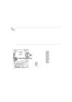
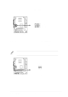
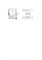
5. USB header (10-1 pin USB2) If the USB ports on the rear panel are inadequate, a USB header is available for two additional USB ports. Connect a 2-port USB connector set to the USB header and mount the USB bracket to an open slot in the chassis. USB Power USBP2- USBP2+ GND NC USB2 P4B-FX 1 5 6 10 USB Power USBP3- USBP3+ GND P4B-FX USB Header Figure 2-29 USB Header 6. Infrared module connector (5-1 pin IR_CN) This connector supports an optional wireless transmitting and receiving infrared module. This module mounts to a small opening on system chassis that support this feature. Use the five pins as shown in Back View and connect a ribbon cable from the module to the motherboard SIR connector according to the pin definitions. If you installed an infrared module, enable the UART2 Use Standard Infrared parameter in BIOS to set UART2 for use with IR. See section "4.4.2 I/O Device Configuration" for details. If you enable the onboard infrared feature for use with an infrared module, the COM2 port does not work. IR_CN 1 Front View Back View +5V IRRX GND IRTX P4B-FX P4B-FX Infrared Module Connector Figure 2-30 Infrared Module Connector ASUS P4B-FX motherboard user guide IRTX GND IRRX +5V (NC) 2-23
-
 1
1 -
2
-
3
-
4
-
5
-
6
-
7
-
8
-
9
-
10
-
11
-
12
-
13
-
14
-
15
-
16
-
17
-
18
-
19
-
20
-
21
-
22
-
23
-
24
-
25
-
26
-
27
-
28
-
29
-
30
-
31
-
32
-
33
-
34
-
35
-
36
-
37
-
 38
38 -
 39
39 -
 40
40 -
 41
41 -
 42
42 -
 43
43 -
 44
44 -
 45
45 -
 46
46 -
 47
47 -
 48
48 -
49
-
50
-
51
-
52
-
53
-
54
-
55
-
56
-
57
-
58
-
59
-
60
-
61
-
62
-
63
-
64
-
65
-
66
-
67
-
68
-
69
-
70
-
71
-
72
-
73
-
74
-
75
-
76
-
77
-
78
-
79
-
80
-
81
-
82
-
83
-
84
-
85
-
86
-
87
-
88
-
89
-
90
-
91
-
92
-
93
-
94
-
95
-
96
-
97
-
98
-
99
-
100
-
101
-
102
-
103
-
104
-
105
-
106
-
107
-
108
-
109
-
110
-
111
-
112
 |
 |
