Asus P4SGL-VM P4SGL-VM User Manual - Page 18
controllers, IDE Master/Slave controllers, and the MuTIOL Connect - cpu support
 |
View all Asus P4SGL-VM manuals
Add to My Manuals
Save this manual to your list of manuals |
Page 18 highlights
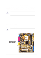
1 ATX 12V connector. This power connector connects the 4-pin 12V plug from the ATX 12V power supply. 2 CPU socket. A 478-pin surface mount, Zero Insertion Force (ZIF) socket called mPGA478. This socket accommodates the Intel® Pentium® 4 478/Northwood Processor with 400MHz system bus. 3 North bridge controller. This SiS650GL controller integrates a high performance host interface for the Intel Pentium 4 processor, a memory controller, and SiS MuTIOL technology. 4 ATX power connector. This 20-pin connector connects to an ATX +12V power supply. The power supply must have at least 1A on the +5V standby lead (+5VSB). 5 DDR DIMM sockets. These two 184-pin DIMM sockets support up to 2GB using unbuffered non-ECC PC2100/1600 DDR DIMMs. 6 IDE connectors. These dual-channel bus master IDE connectors support up to four Ultra DMA/133/100/66, PIO Modes 3 & 4 IDE devices. Both the primary (blue) and secondary (black) connectors are slotted to prevent incorrect insertion of the IDE ribbon cable. 7 South bridge controller. Referred to as the SiS961B MuTIOL Media I/O, this controller integrates the audio controller with AC'97 Interface, Ethernet MAC, Dual Universal Serial Bus Host controllers, IDE Master/Slave controllers, and the MuTIOL Connect to PCI Bridge. 8 ASUS ASIC. This chip performs multiple system functions that include hardware and system voltage monitoring. 9 Onboard LED This green indicator light informs the user that power is being supplied to the board. 10 Floppy disk connector. This connector accommodates the provided ribbon cable for the floppy disk drive. One side of the connector is slotted to prevent incorrect insertion of the floppy disk cable. 11 Flash EEPROM. This 2Mb firmware contains the programmable BIOS program. 12 Super I/O controller. This Low Pin Count (LPC) interface provides the commonly used Super I/O functionality. The chipset supports a high-performance floppy disk controller for a 360K/720K/1.44M/ 2.88M floppy disk drive, a multi-mode parallel port, two standard compatible UARTs, a Standard Infrared (SIR), one MPU-401 UART mode compatible MIDI/game port, and a Flash ROM interface. 13 PCI slots. These three 32-bit PCI 2.2 expansion slots support bus master PCI cards like SCSI or LAN cards with 133MB/s maximum throughput. 1-6 Chapter 1: Product introduction
-
 1
1 -
2
-
3
-
4
-
5
-
6
-
7
-
8
-
9
-
10
-
11
-
12
-
 13
13 -
 14
14 -
 15
15 -
 16
16 -
 17
17 -
 18
18 -
 19
19 -
 20
20 -
 21
21 -
 22
22 -
 23
23 -
24
-
25
-
26
-
27
-
28
-
29
-
30
-
31
-
32
-
33
-
34
-
35
-
36
-
37
-
38
-
39
-
40
-
41
-
42
-
43
-
44
-
45
-
46
-
47
-
48
-
49
-
50
-
51
-
52
-
53
-
54
-
55
-
56
-
57
-
58
-
59
-
60
-
61
-
62
-
63
-
64
-
65
-
66
-
67
-
68
-
69
-
70
-
71
-
72
-
73
-
74
-
75
-
76
-
77
-
78
-
79
-
80
-
81
-
82
-
83
-
84
-
85
-
86
-
87
-
88
-
89
-
90
-
91
-
92
-
93
-
94
-
95
-
96
-
97
-
98
-
99
-
100
-
101
-
102
-
103
-
104
-
105
-
106
-
107
-
108
-
109
-
110
-
111
-
112
-
113
-
114
-
115
-
116
-
117
-
118
-
119
-
120
 |
 |
