Asus P5G41-M LX2 User Manual - Page 22
P5G41-M LX SATA connectors
 |
View all Asus P5G41-M LX2 manuals
Add to My Manuals
Save this manual to your list of manuals |
Page 22 highlights
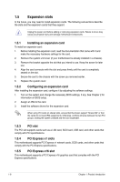
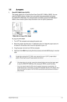
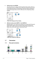
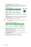
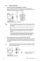
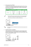
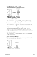
3. IDE connector (40-1 pin PRI_IDE) The onboard IDE connector is for the Ultra DMA 100/66 signal cable. There are three connectors on each Ultra DMA 100/66 signal cable: blue, black, and gray. Connect the blue connector to the motherboard's IDE connector, then select one of the following modes to configure your device. Single device Two devices Drive jumper setting Cable-Select or Master Cable-Select Master Slave Mode of device(s) - Master Slave Master Slave Cable connector Black Black Gray Black or gray • Pin 20 on the IDE connector is removed to match the covered hole on the Ultra DMA cable connector. This prevents incorrect insertion when you connect the IDE cable. • Use the 80-conductor IDE cable for Ultra DMA 100/66 IDE devices. PRI_IDE P5G41-M LX PIN1 NOTE:Orient the red markings on the IDE ribbon cable to PIN 1. P5G41-M LX IDE connector If any device jumper is set as "Cable-Select," ensure that all other device jumpers have the same setting. 4. Serial ATA connectors (7-pin SATA1-4) These connectors are for the Serial ATA signal cables for Serial ATA 3Gb/s hard disk drives and optical disk drives. The Serial ATA 3Gb/s is backward compatible with the Serial ATA 1.5Gb/s specification. The data transfer rate of the Serial ATA 3Gb/s is faster than the standard parallel ATA (133 MB/s). P5G41-M LX GND RSATA_RXN1 RSATA_RXP1 GND RSATA_TXN1 RSATA_TXP1 GND GND RSATA_RXN3 RSATA_RXP3 GND RSATA_TXN3 RSATA_TXP3 GND SATA1 SATA3 SATA4 GND RSATA_TXP4 RSATA_TXN4 GND RSATA_RXP4 RSATA_RXN4 GND SATA2 GND RSATA_TXP2 RSATA_TXN2 GND RSATA_RXP2 RSATA_RXN2 GND P5G41-M LX SATA connectors ASUS P5G41-M LX 1-13
-
 1
1 -
2
-
3
-
4
-
5
-
6
-
7
-
8
-
9
-
10
-
11
-
12
-
13
-
14
-
15
-
16
-
 17
17 -
 18
18 -
 19
19 -
 20
20 -
 21
21 -
 22
22 -
 23
23 -
 24
24 -
 25
25 -
 26
26 -
 27
27 -
28
-
29
-
30
-
31
-
32
-
33
-
34
-
35
-
36
-
37
-
38
-
39
-
40
 |
 |
