Asus P5GD1-VM P5GD1-VM User's manual English Edition E1671 - Page 23
System memory
 |
View all Asus P5GD1-VM manuals
Add to My Manuals
Save this manual to your list of manuals |
Page 23 highlights
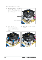
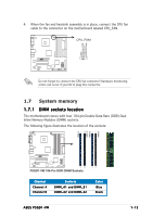
P5GD1-VM GND CPU FAN PWR CPU FAN IN CPU FAN PWM 4. When the fan and heatsink assembly is in place, connect the CPU fan cable to the connector on the motherboard labeled CPU_FAN. CPU_FAN1 ® Do not forget to connect the CPU fan connector! Hardware monitoring errors can occur if you fail to plug this connector. 1.7 System memory 1.7.1 DIMM sockets location The motherboard comes with four 184-pin Double Data Rate (DDR) Dual Inline Memory Modules (DIMM) sockets. The following figure illustrates the location of the sockets: P5GD1-VM DIMM_A1 DIMM_A2 DIMM_B1 DIMM_B2 ® P5GD1-VM 184-Pin DDR DIMM Sockets Channel Channel A Channel B Sockets DIMM_A1 and DIMM_B1 DIMM_A2 and DIMM_B2 Color Blue Black ASUS P5GD1-VM 1-13
-
 1
1 -
2
-
3
-
4
-
5
-
6
-
7
-
8
-
9
-
10
-
11
-
12
-
13
-
14
-
15
-
16
-
17
-
 18
18 -
 19
19 -
 20
20 -
 21
21 -
 22
22 -
 23
23 -
 24
24 -
 25
25 -
 26
26 -
 27
27 -
 28
28 -
29
-
30
-
31
-
32
-
33
-
34
-
35
-
36
-
37
-
38
-
39
-
40
-
41
-
42
-
43
-
44
-
45
-
46
-
47
-
48
-
49
-
50
-
51
-
52
-
53
-
54
-
55
-
56
-
57
-
58
-
59
-
60
-
61
-
62
-
63
-
64
-
65
-
66
-
67
-
68
-
69
-
70
-
71
-
72
-
73
-
74
-
75
-
76
-
77
-
78
-
79
-
80
-
81
-
82
-
83
-
84
-
85
-
86
-
87
-
88
 |
 |
ASUS P5GD1-VM
ASUS P5GD1-VM
ASUS P5GD1-VM
ASUS P5GD1-VM
ASUS P5GD1-VM
1-13
1-13
1-13
1-13
1-13
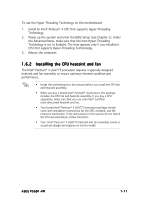
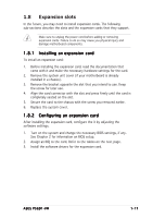
1.7
System memory
1.7.1
1.7.1
1.7.1
1.7.1
1.7.1
DIMM sockets location
DIMM sockets location
DIMM sockets location
DIMM sockets location
DIMM sockets location
The motherboard comes with four 184-pin Double Data Rate (DDR) Dual
Inline Memory Modules (DIMM) sockets.
The following figure illustrates the location of the sockets:
P5GD1-VM
P5GD1-VM 184-Pin DDR DIMM Sockets
DIMM_A1
DIMM_A2
DIMM_B1
DIMM_B2
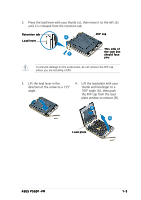
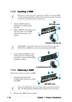
4.
When the fan and heatsink assembly is in place, connect the CPU fan
cable to the connector on the motherboard labeled CPU_FAN.
Do not forget to connect the CPU fan connector! Hardware monitoring
errors can occur if you fail to plug this connector.
P5GD1-VM
CPU_FAN1
GND
CPU FAN PWR
CPU FAN IN
CPU FAN PWM
Channel
Channel
Channel
Channel
Channel
Sockets
Sockets
Sockets
Sockets
Sockets
Color
Color
Color
Color
Color
Channel A
Channel A
Channel A
Channel A
Channel A
DIMM_A1 and DIMM_B1
DIMM_A1 and DIMM_B1
DIMM_A1 and DIMM_B1
DIMM_A1 and DIMM_B1
DIMM_A1 and DIMM_B1
Blue
Blue
Blue
Blue
Blue
Channel B
Channel B
Channel B
Channel B
Channel B
DIMM_A2 and DIMM_B2
DIMM_A2 and DIMM_B2
DIMM_A2 and DIMM_B2
DIMM_A2 and DIMM_B2
DIMM_A2 and DIMM_B2
Black
Black
Black
Black
Black