Asus P5N32-E SLI Plus P5N32-E SLI Plus User''s Manual for English Edtion - Page 54
USB connectors, 1 pin USB56, USB78, USB910 - sata
 |
View all Asus P5N32-E SLI Plus manuals
Add to My Manuals
Save this manual to your list of manuals |
Page 54 highlights
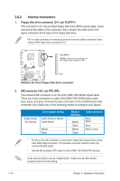
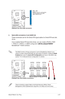
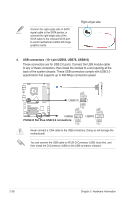
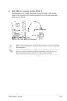
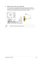
Connect the right-angle side of SATA signal cable to the SATA device, or connect the right‑angle side of the SATA cable to the onboard SATA port to avoid mechanical conflict with huge graphics cards. Right-angle side 4. USB connectors (10-1 pin USB56, USB78, USB910) These connectors are for USB 2.0 ports. Connect the USB module cable to any of these connectors, then install the module to a slot opening at the back of the system chassis. These USB connectors comply with USB 2.0 specification that supports up to 480 Mbps connection speed. NC GND USB_P6+ USB_P6USB+5V NC GND USB_P8+ USB_P8USB+5V USB910 ® 1 GND USB_P5+ USB_P5USB+5V NC GND USB_P6+ USB_P6- USB+5V P5N32-E SLI Plus USB56 P5N32-E SLI Plus USB 2.0 connectors 1 USB78 1 GND USB_P7+ USB_P7USB+5V GND USB_P5+ USB_P5USB+5V Never connect a 1394 cable to the USB connectors. Doing so will damage the motherboard! You can connect the USB cable to ASUS Q-Connector (USB, blue) first, and then install the Q-Connector (USB) to the USB connector onboard. 2-28 Chapter 2: Hardware information
-
 1
1 -
2
-
3
-
4
-
5
-
6
-
7
-
8
-
9
-
10
-
11
-
12
-
13
-
14
-
15
-
16
-
17
-
18
-
19
-
20
-
21
-
22
-
23
-
24
-
25
-
26
-
27
-
28
-
29
-
30
-
31
-
32
-
33
-
34
-
35
-
36
-
37
-
38
-
39
-
40
-
41
-
42
-
43
-
44
-
45
-
46
-
47
-
48
-
 49
49 -
 50
50 -
 51
51 -
 52
52 -
 53
53 -
 54
54 -
 55
55 -
 56
56 -
 57
57 -
 58
58 -
 59
59 -
60
-
61
-
62
-
63
-
64
-
65
-
66
-
67
-
68
-
69
-
70
-
71
-
72
-
73
-
74
-
75
-
76
-
77
-
78
-
79
-
80
-
81
-
82
-
83
-
84
-
85
-
86
-
87
-
88
-
89
-
90
-
91
-
92
-
93
-
94
-
95
-
96
-
97
-
98
-
99
-
100
-
101
-
102
-
103
-
104
-
105
-
106
-
107
-
108
-
109
-
110
-
111
-
112
-
113
-
114
-
115
-
116
-
117
-
118
-
119
-
120
-
121
-
122
-
123
-
124
-
125
-
126
-
127
-
128
-
129
-
130
-
131
-
132
-
133
-
134
-
135
-
136
-
137
-
138
-
139
-
140
-
141
-
142
-
143
-
144
-
145
-
146
-
147
-
148
-
149
-
150
-
151
-
152
-
153
-
154
-
155
-
156
-
157
-
158
 |
 |
