Asus P5N7A-VM User Manual
Asus P5N7A-VM - Motherboard - Micro ATX Manual
 |
UPC - 610839163564
View all Asus P5N7A-VM manuals
Add to My Manuals
Save this manual to your list of manuals |
Asus P5N7A-VM manual content summary:
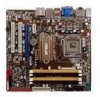
- Asus P5N7A-VM | User Manual - Page 1
P5N7A-VM Motherboard - Asus P5N7A-VM | User Manual - Page 2
express written permission of ASUSTeK COMPUTER INC. ("ASUS"). Product warranty or service will not be extended if: (1) the ASUS HAS BEEN ADVISED OF THE POSSIBILITY OF SUCH DAMAGES ARISING FROM ANY DEFECT OR ERROR IN THIS MANUAL OR PRODUCT. SPECIFICATIONS AND INFORMATION CONTAINED IN THIS MANUAL - Asus P5N7A-VM | User Manual - Page 3
About this guide viii P5N7A-VM specifications summary x Chapter 1: Product introduction 1.1 Welcome 1-2 1.2 Package contents 1-2 1.3 Special features 1-2 1.3.1 Product highlights 1-2 1.3.2 ASUS Special Features 1-5 1.3.3 ASUS Stylish Features 1-7 1.3.4 ASUS Intelligent Overclocking features - Asus P5N7A-VM | User Manual - Page 4
30 Chapter 2: BIOS setup 2.1 Managing and updating your BIOS 2-2 2.1.1 ASUS Update utility 2-2 2.1.2 Creating a bootable floppy disk 2-5 2.1.3 ASUS EZ Flash 2 utility 2-6 2.1.4 AFUDOS utility 2-7 2.1.5 ASUS CrashFree BIOS 3 utility 2-9 2.2 BIOS setup program 2-11 2.2.1 BIOS menu screen 2-12 - Asus P5N7A-VM | User Manual - Page 5
3.2.4 Manual menu 3-7 3.2.5 ASUS Contact information 3-7 3.2.6 Other information 3-8 3.3 Software information 3-10 ASUS Express Gate 3-10 3.4 Creating a RAID driver disk 3-19 3.4.1 Creating a RAID driver disk without entering the OS.... 3-19 3.4.2 Creating a RAID driver disk in Windows 3-19 - Asus P5N7A-VM | User Manual - Page 6
must accept any interference received including interference that may cause undesired operation. This equipment has been tested and found to comply with the limits for a Class B digital device, pursuant to Part 15 of the FCC Rules. These limits are designed to provide reasonable protection against - Asus P5N7A-VM | User Manual - Page 7
qualified service technician or your retailer. Operation safety • Before installing the motherboard and adding devices on it, carefully read all the manuals stable surface. • If you encounter technical problems with the product, contact a qualified service technician or your retailer. This symbol of - Asus P5N7A-VM | User Manual - Page 8
the BIOS parameters are also provided. • Chapter 3: Software support This chapter describes the contents of the support DVD that comes with the motherboard package. Where to find more information Refer to the following sources for additional information and for product and software updates. 1. ASUS - Asus P5N7A-VM | User Manual - Page 9
the following symbols used throughout this manual. DANGER/WARNING: Information to prevent injury to yourself when trying to complete a task. CAUTION: Information to prevent damage to the components when trying to complete a task. IMPORTANT: Instructions that you MUST follow to complete - Asus P5N7A-VM | User Manual - Page 10
P5N7A-VM specifications summary CPU Chipset System bus Memory Graphics Expansion slots LAN USB LGA775 socket for Intel® Core™2 Quad/Core™2 Extreme/Core™2 Duo/Pentium® dual-core/Celeron® dual-core/Celeron® processors Compatible with Intel® 05B/05A/06 processors Supports Intel® next-generation 45nm - Asus P5N7A-VM | User Manual - Page 11
P5N7A-VM specifications summary Storage Audio ASUS Special Features ASUS Overclocking features Internal connectors Southbridge - 5 x Serial ATA 3.0 Gb/s ports - 1 x External SATA 3Gb/s port - Supports RAID 0, RAID 1, RAID 5, RAID 0+1, and JBOD configuration JMicron® JMB368 PATA controller - Asus P5N7A-VM | User Manual - Page 12
P5N7A-VM specifications summary Rear panel connectors BIOS features Manageability Accessories Support DVD contents Form factor 1 x PS/2 keyboard/mouse combo port 1 x VGA port 1 x Optical S/PDIF Out port 1 x DisplayPort 1 x HDMI port 1 x DVI port 1 x External SATA port 1 x LAN (RJ-45) port 6 x USB - Asus P5N7A-VM | User Manual - Page 13
This chapter describes the motherboard features and the new technologies it supports. Chapter 1: 1Product introduction - Asus P5N7A-VM | User Manual - Page 14
ASUS P5N7A-VM Cables Serial ATA signal cable for 2 devices Serial ATA power cable for 2 devices 1 x Ultra DMA 133/100 cable Accessories I/O shield 1 x ASUS Q-Connector Kit (USB, system panel; Retail version only) Application DVD ASUS motherboard support DVD Documentation User guide - Asus P5N7A-VM | User Manual - Page 15
NVIDIA GeForce 9300 Chipset The NVIDIA GeForce® 9300 motherboard GPU is the industry's first desktop PC singlechip solution for Intel CPUs integrating multiple dedicated processors for DirectX 10 shader model 4.0 3D graphics and PureVideo® HD processor, SLI technology, storage, communications audio, - Asus P5N7A-VM | User Manual - Page 16
motherboard supports the latest PCI Express 2.0 devices for double speed and bandwidth which enhances system performance.See page 1-26 for details. Serial ATA 3Gb/s technology The motherboard supports SATA hard drives based on the new SATA 3Gb/s storage specification. It allows RAID 0, RAID 1, RAID - Asus P5N7A-VM | User Manual - Page 17
display devices such as LCD monitor. The interface of this motherboard is HDCP compliant, allowing playback of HD DVD, Blu-ray Disc and other protected content. 1.3.2 ASUS Special Features ASUS Quiet Thermal Solution ASUS Quiet Thermal solution makes system more stable and enhances the overclocking - Asus P5N7A-VM | User Manual - Page 18
easy ways to install computer components, update the BIOS or back up your favorite settings. ASUS Q-Connector ASUS Q-Connector allows you to easily connect or disconnect the chassis front panel cables to the motherboard. This unique module eliminates the trouble of connecting the system panel cables - Asus P5N7A-VM | User Manual - Page 19
configuration, and product model. • ASUS Express Gate supports file uploading from SATA HDDs, ODDs and USB drive and downloading to USB drives only. 1.3.4 ASUS Intelligent Overclocking features C.P.R. (CPU Parameter Recall) The C.P.R. feature of the motherboard BIOS allows automatic re-setting to - Asus P5N7A-VM | User Manual - Page 20
that you should shut down the system and unplug the power cable before removing or plugging in any motherboard component. The illustration below shows the location of the onboard LED. P5N7A-VM P5N7A-VM Onboard LED SB_PWR ON Standby Power OFF Powered Off 1-8 Chapter 1: Product Introduction - Asus P5N7A-VM | User Manual - Page 21
as indicated in the image below. 1.5.2 Screw holes Place six (6) screws into the holes indicated by circles to secure the motherboard to the chassis. Do not overtighten the screws! Doing so can damage the motherboard. Place this side towards the rear of the chassis P5N7A-VM ASUS P5N7A-VM 1-9 - Asus P5N7A-VM | User Manual - Page 22
FLOPPY 24.4cm (9.6in) 1.5.3 Motherboard layout 23.4cm (9.2in) KB/MS_USB56 SPDIFO_ HDMI_ DP_ ATX12V LGA775 PWR_FAN CPU_FAN Super I/O COM1 VGA_DVI F_ ESATA_ USB34 LAN1_USB12 CHA_FAN AUDIO 8Mb BIOS MCP7A-S CLRTC PCIEX1_1 CR2032 3V Lithium Cell CMOS Power P5N7A-VM RTL 8211CL PCIEX16 - Asus P5N7A-VM | User Manual - Page 23
/loss/ incorrect removal of the PnP cap. 1.6.1 Installling the CPU To install a CPU: 1. Locate the CPU socket on the motherboard. P5N7A-VM P5N7A-VM CPU Socket 775 Before installing the CPU, ensure that the socket box is facing towards you and the load lever is on your left. ASUS P5N7A-VM 1-11 - Asus P5N7A-VM | User Manual - Page 24
PnP Cap B This side of the cam box should face you. To prevent damage to the socket pins, do not remove the PnP cap unless you are installing a CPU. 3. Lift the load lever in then push the PnP cap from the load plate window to remove (B). B A Load plate 1-12 Chapter 1: Product Introduction - Asus P5N7A-VM | User Manual - Page 25
only one correct orientation. DO NOT force the CPU into the socket to prevent bending the connectors on the socket and damaging the CPU! The motherboard supports Intel® LGA775 processors with the Enhanced Intel SpeedStep® Technology (EIST), and Hyper‑Threading Technology. ASUS P5N7A-VM 1-13 - Asus P5N7A-VM | User Manual - Page 26
performance. • Install the motherboard to the chassis before you install the CPU fan and heatsink assembly • When you buy a boxed Intel® Core™ Pentium D/Pentium® 4/Celeron® LGA775 heatsink and fan assembly comes in a push-pin design and requires no tool to install. If you purchased a separate CPU - Asus P5N7A-VM | User Manual - Page 27
connector on the motherboard labeled CPU_FAN. P5N7A-VM P5N7A-VM CPU Fan Connector • Do not forget to connect the CPU fan connector! Hardware monitoring errors can occur if you fail to plug this connector. • We recommend you to install the chassis fan for better thermal state. ASUS P5N7A-VM 1-15 - Asus P5N7A-VM | User Manual - Page 28
the CPU heatsink and fan To uninstall the CPU heatsink and fan: 1. Disconnect the CPU fan cable from the connector on the motherboard. 2. Rotate each fastener counterclockwise. 3. Pull up two fasteners at a time in a diagonal sequence to disengage the heatsink and fan assembly B from the - Asus P5N7A-VM | User Manual - Page 29
.) Narrow end of the groove Refer to the documentation in the boxed or stand-alone CPU fan package for detailed information on CPU fan installation. ASUS P5N7A-VM 1-17 - Asus P5N7A-VM | User Manual - Page 30
System memory 1.7.1 Overview The motherboard comes with four Double Data Rate 2 (DDR2) Dual Inline Memory Modules (DIMM) sockets. The figure illustrates the location of the DDR2 DIMM sockets: DIMM_B1 DIMM_B2 DIMM_A1 DIMM_A2 128 Pins 112 Pins P5N7A-VM P5N7A-VM 240-pin DDR2 DIMM Sockets Channel - Asus P5N7A-VM | User Manual - Page 31
vendor to check the ODT value. • Due to chipset limitation, DDR2-800 with CL=4 will be downgraded to run at DDR2-667 by default setting. If you want to operate with lower latency, adjust the memory timing manually. P5N7A-VM Motherboard Qualified Vendors Lists (QVL) DDR2-667MHz capability Size - Asus P5N7A-VM | User Manual - Page 32
N/A Kingston SS/ DS Chip No. DS Heat-Sink Package SS Heat-Sink Package DS Heat-Sink Package DIMM support A* B* C* • • • • • • • • KVR800D2N6/512 KVR800D2N6/1G KVR800D2N5/2G N/A Elpida SS E5108AJBG-8E-E • • • N/A Elpida DS E5108AJBG-8E-E • • • N/A Elpida DS E1108ACBG-8E - Asus P5N7A-VM | User Manual - Page 33
DS GL2L64M088BA30EB DS GL2L64M088BA30EB DIMM support • • • • • • • • • • • • • • • • • • • • • • • • • • • • • • • • • • • • • • • • • • • • • • • • • • • • • • • • • • • • • • • (continued on the next page) ASUS P5N7A-VM 1-21 - Asus P5N7A-VM | User Manual - Page 34
or the black slots as one pair of Dual-channel memory configuration. • C*: Supports four modules inserted into both the yellow and black slots as two pairs of Dual-channel memory configuration. Visit the ASUS website for the latest DDR2-667/800 MHz QVL. 1-22 Chapter 1: Product Introduction - Asus P5N7A-VM | User Manual - Page 35
can cause severe damage to both the motherboard and the components. To install a Support the DIMM lightly with your fingers when pressing the retaining clips. The DIMM might get damaged when it flips out with extra force. 1 2. Remove the DIMM from the socket. 2 1 DDR2 DIMM notch ASUS P5N7A-VM - Asus P5N7A-VM | User Manual - Page 36
support. Ensure to unplug the power cord before adding or removing expansion cards. Failure to do so may cause you physical injury and damage motherboard system unit cover (if your motherboard is already installed in a chassis BIOS settings, if any. See Chapter 2 for information on BIOS setup - Asus P5N7A-VM | User Manual - Page 37
1 Onboard LAN Onboard SATA controller Onboard HD Audido Onboard VGA MCP _USB shared - shared - - - - - MCP _MAC - - - - shared - - - MCP _AZA - - - - - - shared - MCP _IGPU shared MCP _IDE - - - - - - - MCP _USB2 - shared - shared - - - - MCP _AHCI - - - - - shared - - ASUS P5N7A-VM 1-25 - Asus P5N7A-VM | User Manual - Page 38
1.8.4 PCI slots The PCI slots support cards such as a LAN card, SCSI card, USB card, and other cards that comply with PCI specifications. The figure shows a LAN card installed on a PCI slot. 1.8.5 PCI Express x1 slot This motherboard supports PCI Express x1 network cards, SCSI cards and other cards - Asus P5N7A-VM | User Manual - Page 39
Clear RTC You do not need to clear the RTC when the system hangs due to overclocking. For system failure due to overclocking, use the C.P.R. (CPU Parameter Recall) feature. Shut down and reboot the system so the BIOS can automatically reset parameter settings to default values. ASUS P5N7A-VM 1-27 - Asus P5N7A-VM | User Manual - Page 40
pin Universal Serial Bus (USB) ports are available for connecting USB 2.0 devices. 5. LAN (RJ-45) port. Supported by Gigabit LAN controller, this port allows Gigabit connection to a Local Area Network (LAN) through a network the tape, CD, DVD player, or other audio sources. 9. Line Out port (lime). - Asus P5N7A-VM | User Manual - Page 41
ports, each controller can drive same or different display contents to different resolutions and refresh rates. • Due to the chipset limitation, simultaneous output for DVI and HDMI is not supported. • To play HD DVD or Blu-Ray Disc, ensure to use an HDCP compliant monitor. ASUS P5N7A-VM 1-29 - Asus P5N7A-VM | User Manual - Page 42
system. • Due to chipset limitation, DisplayPort on this motherboard only supports video signals. • DisplayPort does not support HDMI/DVI on this motherboard. 17. USB 2.0 ports 5 and 6. These two 4-pin Universal Serial Bus (USB) ports are available for connecting USB 2.0 devices. 1.10.2 Internal - Asus P5N7A-VM | User Manual - Page 43
at the back of the system chassis. The serial port bracket (COM1) is purchased separately. P5N7A-VM COM1 PIN1 P5N7A-VM COM Port Connector 3. Digital audio connector (4-1 pin SPDIF_OUT for ASUS HDMI VGA card) This connector is for an additional Sony/Philips Digital Interface (S/PDIF) port(s). If - Asus P5N7A-VM | User Manual - Page 44
insertion when you connect the IDE cable. • Use the 80-conductor IDE cable for Ultra DMA 133/100 IDE devices. If any device jumper is set as "Cable-Select," ensure all other device jumpers have the same setting. PRI_IDE P5N7A-VM P5N7A-VM IDE Connector 1-32 Chapter 1: Product Introduction - Asus P5N7A-VM | User Manual - Page 45
conflict with huge graphics cards. • SATA 5 and SATA 6 connectors support AHCI mode and RAID mode only. Ensure to install the AHCI driver or RAID driver in the bundled support DVD before connecting devices to SATA 5 and SATA 6 connectors; otherwise, the devices will not work. ASUS P5N7A-VM 1-33 - Asus P5N7A-VM | User Manual - Page 46
6. LPT connector (26-1 pin LPT) The LPT (Line Printing Terminal) connector supports devices such as a printer. LPT standardizes as IEEE 1394, which is the parallel port interface on IBM PC-compatible computers. P5N7A-VM LPT 1 STB# PD0 PD1 PD2 PD3 PD4 PD5 PD6 PD7 ACK# BUSY PE SLCT AFD ERR# INIT# - Asus P5N7A-VM | User Manual - Page 47
P5N7A-VM Internal Audio Connector 9. CPU, chassis, and power fan connectors (4-pin CPU_FAN, 3-pin CHA_FAN, 3-pin PWR_FAN) The fan connectors support cooling fans of 350 mA~2000 mA (24 W max.) or a total of 1 A~7 A (84 W max.) at +12V. Connect the fan cables to the fan connectors on the motherboard - Asus P5N7A-VM | User Manual - Page 48
HP_R Jack_Sense HP_L P5N7A-VM Azalia Analog Front Panel Connector • We recommend that you connect a high-definition front panel audio module to this connector to avail of the motherboard's high-definition audio capability. • If you want to connect a high-definition front panel audio module to this - Asus P5N7A-VM | User Manual - Page 49
is inadequate. • The ATX 12 V Specification 2.0-compliant (400W) PSU has been tested to support the motherboard power requirements with the following configuration: CPU: Intel® Pentium® Extreme 3.73GHz Memory: 512 MB DDR2 (x4) Graphics card: ASUS EAX1900XT Parallel ATA device: IDE hard disk drive - Asus P5N7A-VM | User Manual - Page 50
(20-8 pin PANEL) This connector supports several chassis-mounted functions. PANEL PLED SPEAKER PLED+ PLED+5V Ground Ground Speaker P5N7A-VM IDE_LED+ IDE_LED- PWR Ground Reset Ground +IDE_LED P5N7A-VM System Panel Connector Reset PWRSW • System power LED (2-pin PLED) This 2-pin connector is - Asus P5N7A-VM | User Manual - Page 51
to the respective front panel cable labels. 2. Install the ASUS Q-Connector to the system panel connector, ensuring the orientation matches the labels on the motherboard. Enable the front panel functions. The figure shows the Q-Connector properly installed on the motherboard. ASUS P5N7A-VM 1-39 - Asus P5N7A-VM | User Manual - Page 52
1-40 Chapter 1: Product Introduction - Asus P5N7A-VM | User Manual - Page 53
This chapter tells how to change the system settings through the BIOS Setup menus. Detailed descriptions of the BIOS parameters are also provided. Chapter 2: 2 BIOS setup - Asus P5N7A-VM | User Manual - Page 54
DVD that comes with the motherboard package. ASUS Update requires an Internet connection either through a network or an Internet Service Provider (ISP). Installing ASUS Update To install ASUS Update: 1. Place the support DVD in the optical drive. The Drivers menu appears. 2. Click the Utilities - Asus P5N7A-VM | User Manual - Page 55
> Programs > ASUS > ASUSUpdate > ASUSUpdate. The ASUS Update main window appears. 2. Select Update BIOS from the 3. Select the ASUS FTP site nearest Internet option from the drop‑down you to avoid network traffic, or menu, then click Next. click Auto Select. Click Next. ASUS P5N7A-VM 2-3 - Asus P5N7A-VM | User Manual - Page 56
The ASUS Update main window appears. 2. Select Update BIOS from a file option from the drop‑down menu, then click Next. 3. Locate the BIOS file from the Open window, then click Open. 4. Follow the screen instructions to complete the update process. P5N7AVM.rom P5N7AVM 2-4 Chapter 2: BIOS setup - Asus P5N7A-VM | User Manual - Page 57
type format A:/S then press . Windows® XP environment a. Insert a 1.44 MB floppy disk to the floppy disk drive. b. Click Start from the Windows® desktop, then select My Computer. Start. 2. Copy the original or the latest motherboard BIOS file to the bootable floppy disk. ASUS P5N7A-VM 2-5 - Asus P5N7A-VM | User Manual - Page 58
so it is accessible by pressing + during the Power-On Self Tests (POST). To update the BIOS using EZ Flash 2: 1. Visit the ASUS website (www.asus.com) to download the latest BIOS file for the motherboard. 2. Save the BIOS file to a floppy disk or a USB flash disk, then restart the system - Asus P5N7A-VM | User Manual - Page 59
returns to the DOS prompt after copying the current BIOS file. Updating the BIOS file To update the BIOS file using the AFUDOS utility: 1. Visit the ASUS website (www.asus.com) and download the latest BIOS file for the motherboard. Save the BIOS file to a bootable floppy disk. ASUS P5N7A-VM 2-7 - Asus P5N7A-VM | User Manual - Page 60
You need to type the exact BIOS filename at the DOS prompt. 2. Copy the AFUDOS utility (afudos.exe) from the motherboard support DVD to the bootable floppy disk verifies the file and starts updating the BIOS. A:\>afudos /iP5N7AVM.ROM AMI Firmware Update Utility - Version 1.19(ASUS V2.07(03.11.24BB - Asus P5N7A-VM | User Manual - Page 61
floppy disk or the USB flash disk that contains the updated BIOS file. • Prepare the motherboard support DVD, the floppy disk, or the USB flash disk containing the updated motherboard BIOS before using this utility. • For the P5N7A-VM motherboard, this utility will not function when you use a PATA - Asus P5N7A-VM | User Manual - Page 62
found! Reading file "P5N7AVM.ROM". Completed. Start flashing... 4. Restart the system after the utility completes the updating process. The recovered BIOS may not be the latest BIOS version for this motherboard. Visit the ASUS website (www.asus.com) to download the latest BIOS file. Recovering the - Asus P5N7A-VM | User Manual - Page 63
under the Exit Menu. See section "2.8 Exit Menu." • The BIOS setup screens shown in this section are for reference purposes only, and may not exactly match what you see on your screen. • Visit the ASUS website (www.asus.com) to download the latest BIOS file for this motherboard. ASUS P5N7A-VM 2-11 - Asus P5N7A-VM | User Manual - Page 64
menu screen Menu items Menu bar Main Advanced Power Configuration fields BIOS SETUP UTILITY Boot Tools Exit General help System Time System Date Legacy Diskette A SATA 1 SATA 2 ESATA SATA 4 [ settings. Some of the navigation keys differ from one screen to another. 2-12 Chapter 2: BIOS setup - Asus P5N7A-VM | User Manual - Page 65
2.2.4 Menu items The highlighted item on the menu bar displays the specific items for that menu. For example, selecting Main shows the Main menu items. The other items ( top right corner of the menu screen is a brief description of the selected item. Pop-up window Scroll bar ASUS P5N7A-VM 2-13 - Asus P5N7A-VM | User Manual - Page 66
for information on the menu screen items and how to navigate through them. Main Advanced Power BIOS SETUP UTILITY Boot Tools Exit System Time System Date Legacy Diskette A SATA 1 SATA 2 ESATA .] [1.2M, 5.25 in.] [720K, 3.5 in.] [1.44M, 3.5 in.] [2.88M, 3.5 in.] 2-14 Chapter 2: BIOS setup - Asus P5N7A-VM | User Manual - Page 67
Disabled], the data transfer from and to the device occurs one sector at a time. Configuration options: [Disabled] [Auto] PIO Mode [Auto] Selects the PIO mode. Configuration options: [Auto] [0] [1] [2] [3] [4] DMA Mode [Auto] Selects the DMA mode. Configuration options: [Auto] ASUS P5N7A-VM 2-15 - Asus P5N7A-VM | User Manual - Page 68
you to select the SATA Mode. Configuration options: [SATA Mode] [RAID Mode] [AHCI Mode] Hard Disk Write Protect [Disabled] Disables or enables device write protection. This will be effective only if device is accessed throuh BIOS. Confiuration option: [Disabled] [Enabled] IDE Detect Time Out (Sec - Asus P5N7A-VM | User Manual - Page 69
Select Item F1 General Help F10 Save and Exit ESC Exit v02.61 (C)Copyright 1985-2008, American Megatrends, Inc. AMI BIOS Displays the auto-detected BIOS information. Processor Displays the auto-detected CPU specification. System Memory Displays the auto-detected system memory. ASUS P5N7A-VM 2-17 - Asus P5N7A-VM | User Manual - Page 70
menu items. Incorrect field values can cause the system to malfunction. Main Advanced Power BIOS SETUP UTILITY Boot Tools Exit CPU Configuration JumperFree Configuration Chipset Onboard Devices Configuration USB Configuration PCIPnP Configure CPU. Select Screen Select Item +- Change Field Tab - Asus P5N7A-VM | User Manual - Page 71
that the BIOS automatically detects. Advanced BIOS SETUP UTILITY value may be different from the set value. C1E Support [Enabled] Allows you to enable or disable Inter Windows XP operating system; set this item to [Enabled] for legacy operating system such as Windows ASUS P5N7A-VM 2-19 - Asus P5N7A-VM | User Manual - Page 72
® 4 or later CPU that supports the Enhanced Intel SpeedStep® Technology Chipset Over voltage CPU Voltage [Auto] [Auto] [Auto] Memory Timings [Auto] [Auto] Set FSB & Memor clock automatically. [Linked] Allows Memory and FSB to overclock proportionally. [Unlink] Enter FSB and Memory clock manually - Asus P5N7A-VM | User Manual - Page 73
you to enter an integer value from 450MHz to 999MHz to overclock for GPU. Configuration options: [Min.=450] [Max.=999] Shader OverClock [1200] Allows you to enter an integer value from 1200MHz to 2000MHz to overclock for shader. Configuration options: [Min.=1200] [Max.=2000] ASUS P5N7A-VM 2-21 - Asus P5N7A-VM | User Manual - Page 74
] [Max = 2.24375V] Chipset Over Voltage [Auto] Allows you to set the Chipset Over Voltage. Configuration options: Auto] [Manual] The following items appear only when the Memory Timings item is set to [Manual]. tCL tWR. Configuration options:[Auto] [2] [3] [4] [5] [6] 2-22 Chapter 2: BIOS setup - Asus P5N7A-VM | User Manual - Page 75
[Disabled] Allows you to enable or disable the Hybrid SLI. Configuration options: [Disabled] [Enabled] Primary Graphics Adapter [PCIE VGA Card First] Display Device Priority, from high to low. Configuration options: [PCI VGA Card First] [Internal VGA First] [PCIE VGA Card First] ASUS P5N7A-VM 2-23 - Asus P5N7A-VM | User Manual - Page 76
you to enable or disable all capable devices populated in PCIE slots to retrain to Gen2 speed. Configuration options: [Yes] [No] Realtek GigaBit LAN [Auto] Allows you to disable Realtek GigaBit LAN or set it to auto mode. Configuration options: [Auto] [Disabled] LAN Boot ROM [Disabled] Allows you to - Asus P5N7A-VM | User Manual - Page 77
BIOS SETUP UTILITY Onboard Device Configuraiton Serial Port1 Address Parallel Port Address Parallel Port Mode Parallel Port IRQ AZALIA Audio Front Panel Type SPDIF Mode Setting [3F8/IRQ4] [378] [Normal] [IRQ7] [Auto] [HD Audio] [SPDIF Output] Allows BIOS : [IRQ5] [IRQ7] ASUS P5N7A-VM 2-25 - Asus P5N7A-VM | User Manual - Page 78
AAFP) mode to legacy AC'97 or high-definition audio depending on the audio standard that the front panel audio module supports. Configuration options: [AC97] [HD Audio] SPDIF Mode Setting [SPDIF Output] Allows you to select the SPDIF mode. If the VGA card has HDMI output and need to use SPDIF signal - Asus P5N7A-VM | User Manual - Page 79
options. Advanced USB Configuration USB Devices Enabled: None BIOS SETUP UTILITY Options Disabled Enhanced USB Functions USB 2.0 Controller Legacy USB Support USB 2.0 Controller Mode [Enabled enable the USB 2.0 Controller item. Configuration options: [FullSpeed ] [HiSpeed ] ASUS P5N7A-VM 2-27 - Asus P5N7A-VM | User Manual - Page 80
Help F10 Save and Exit ESC Exit v02.61 (C)Copyright 1985-2007, American Megatrends, Inc. Plug And Play O/S [No] When set to [No], BIOS configures all the devices in the system. When set to [Yes] and if you install a Plug and Play operating system, the operating system configures the Plug and Play - Asus P5N7A-VM | User Manual - Page 81
ACPI 2.0 Support ACPI APIC Support APM Configuration Hardware Monitor BIOS SETUP UTILITY support in the Application-Specific Integrated Circuit (ASIC). When set to Enabled, the ACPI APIC table pointer is included in the RSDT pointer list. Configuration options: [Disabled] [Enabled] ASUS P5N7A-VM - Asus P5N7A-VM | User Manual - Page 82
2.5.4 APM Configuration Power BIOS SETUP UTILITY Restore on AC Power Loss APM Resume Event Configuration Power On PCI Wake Power On PCIE Wake# Power On LAN(MAC) Power On Ring Power On PS/2 Keyboard Power On RTC Alarm [Power Off] [Disabled] [Disabled] [Disabled] [Disabled] [Disabled] [Disabled] - Asus P5N7A-VM | User Manual - Page 83
[Enabled] 2.5.5 Hardware Monitor Power Hardware Monitor BIOS SETUP UTILITY CPU Temperature MB Temperature CPU Fan motherboard, the field shows N/A. CPU Q-Fan Control [Enabled] Allows you to enable or disable the CPU Q-Fan controller. Configuration options: [Disabled] [Enabled] ASUS P5N7A-VM - Asus P5N7A-VM | User Manual - Page 84
in rotations per minute (RPM). If the fan is not connected to the motherboard, the field shows N/A. Chassis Q-Fan Control [Enabled] Allows you to enable in rotations per minute (RPM). If the fan is not connected to the motherboard, the field shows N/A. Vcore Voltage, 3.3V Voltage, 5V Voltage, 12V - Asus P5N7A-VM | User Manual - Page 85
] These items specify the boot device priority sequence from the available devices. The number of device items that appears on the screen depends on the number of devices installed in the system. Configuration options: [1st FLOPPY DRIVE] [Hard Drive] [ATAPI CD_ROM] [Disabled] ASUS P5N7A-VM 2-33 - Asus P5N7A-VM | User Manual - Page 86
Message Display [Enabled] [Enabled] [Force BIOS] [On] [Enabled] [Enabled] Allows BIOS to skip certain tests while booting. This will decrease the time use the ASUS MyLogo 2™ feature. AddOn ROM Display Mode [Force BIOS] Sets the display mode for option ROM. Configuration options: [Force BIOS] [Keep - Asus P5N7A-VM | User Manual - Page 87
forget your BIOS password, you can clear clear it by erasing the CMOS Real Time Clock (RTC) RAM. See section "1.9 Jumper" for information on how to erase the RTC RAM. After you have set a supervisor password, the other items appear to allow you to change other security settings. ASUS P5N7A-VM 2-35 - Asus P5N7A-VM | User Manual - Page 88
Security Settings BIOS SETUP UTILITY Boot Supervisor Password User Password Change Supervisor Password Password Check [Setup] When set to [Setup], BIOS checks for user password when accessing the Setup utility. When set to [Always], BIOS checks for user password both when accessing Setup and - Asus P5N7A-VM | User Manual - Page 89
to run the utility to select and update BIOS. This utility doesn't support : 1.NTFS format Select Screen Select Item +- Change Field Enter Go to Sub Screen F1 General Help F10 Save and Exit ESC Exit v02.61 (C)Copyright 1985-2008, American Megatrends, Inc. 2.7.1 ASUS EZ Flash 2 Allows you to run - Asus P5N7A-VM | User Manual - Page 90
ASUS Express Gate feature. The ASUS Gate's first screen before starting Windows or other installed OS. Choose BIOS. 2.7.3 AI NET 2 AI NET 2 Pair Status BIOS SETUP UTILITY Tools Length Check Realtek Phy LAN cable [Disabled] Check Realtek Phy LAN cable during POST. Check Realtek Phy LAN - Asus P5N7A-VM | User Manual - Page 91
fields other than System Date, System Time, and Password, the BIOS asks for a confirmation before exiting. Discard Changes This option window appears. Select OK to load default values. Select Exit & Save Changes or make other changes before saving the values to the non-volatile RAM. ASUS P5N7A-VM - Asus P5N7A-VM | User Manual - Page 92
2-40 Chapter 2: BIOS setup - Asus P5N7A-VM | User Manual - Page 93
This chapter describes the contents of the support DVD that comes with the motherboard package. Chapter 3: 3 Software support - Asus P5N7A-VM | User Manual - Page 94
. • Ensure that you install Windows® XP Service Pack 2 or later versions before installing the drivers for better compatibility and system stability. 3.2 Support DVD information The support DVD that came with the motherboard package contains the drivers, software applications, and utilities that - Asus P5N7A-VM | User Manual - Page 95
. Norton Internet Security 2008 Installs the Norton Internet Security 2008. NVIDIA nForce Chipset Driver Installs the NVIDIA nForce chipset driver. Realtek Audio Driver Installs the Realtek audio driver and application. ASUS EPU-4 Engine Installs the ASUS EPU-4 Engine driver. ASUS P5N7A-VM 3-3 - Asus P5N7A-VM | User Manual - Page 96
ASUS InstallAll installation wizard for utilities. ASUS Update The ASUS Update utility allows you to update the motherboard BIOS in a Windows® environment. This utility requires an Internet connection either through a network or an Internet Service Provider (ISP). 3-4 Chapter 3: Software support - Asus P5N7A-VM | User Manual - Page 97
problems. This utility helps you keep your computer in healthy operating condition. ASUS AI Nap Installs the ASUS PDF). ASUS Express Gate Installer Installs the ASUS Express Gate. Ulead Burn. Now Installs the Ulead Burn.Now application for Audio DirectX 9.0c driver. The updates. ASUS P5N7A-VM 3-5 - Asus P5N7A-VM | User Manual - Page 98
you to make a RAID driver disk. NVIDIA 32/64bit XP AHCI Driver Allows you to create the NVIDIA 32/64-bit XP AHCI Driver disk for Windows® XP Operating System (OS). NVIDIA 32/64bit Vista AHCI Driver Allows you to create the NVIDIA 32/64-bit Vista AHCI Driver disk for Windows® Vista Operating System - Asus P5N7A-VM | User Manual - Page 99
(PDF). Install the Adobe® Acrobat® Reader from the Utilities menu before opening a user manual file. 3.2.5 ASUS Contact information Click the Contact tab to display the ASUS contact information. You can also find this information on the inside front cover of this user guide. ASUS P5N7A-VM 3-7 - Asus P5N7A-VM | User Manual - Page 100
give additional information on the motherboard and the contents of the support DVD. Click an icon to display the specified information. Motherboard Info Displays the general specifications of the motherboard. Browse this DVD Displays the support DVD contents in graphical format. 3-8 Chapter - Asus P5N7A-VM | User Manual - Page 101
Technical support Form Displays the ASUS Technical Support Request Form that you have to fill out when requesting technical support. Filelist Displays the contents of the support DVD and a brief description of each in text format. ASUS P5N7A-VM 3-9 - Asus P5N7A-VM | User Manual - Page 102
the web browser, Skype, or other Express Gate softwares. Installing ASUS Express Gate • ASUS Express Gate supports installation on SATA HDDs in IDE mode only. • ASUS Express Gate supports HDDs connected to motherboard chipset- controlled onboard SATA ports only. All onboard extended SATA ports and - Asus P5N7A-VM | User Manual - Page 103
to continue. 6. Follow the screen instructions to complete installation. The First to your installed OS such as Windows), enter BIOS setup, or power off. If guide you through basic Express Gate configurations. Basic configurations include language, date and time and screen resolution. ASUS P5N7A-VM - Asus P5N7A-VM | User Manual - Page 104
windows. Bring a window to the foreground by clicking within Re-size a window by dragging any of its four corners. Move a window by dragging its title /BREAK ESC DEL F8 Function Power-off Continue to boot OS Enter BIOS setup Enter Boot selection pop-up In the Express Gate Environment: Key - Asus P5N7A-VM | User Manual - Page 105
docks, whether it auto-hides, etc.) • Network: Specify how your computer connects to the Internet. Enable the network port. LAN1 refers to the RJ-45 network port on your computer. Also specify whether to Control: Control the volume for your speaker output, microphone input, etc. ASUS P5N7A-VM 3-13 - Asus P5N7A-VM | User Manual - Page 106
to open the File Manager window, which lets you conveniently access the files on a USB drive. If a USB device is detected, the icon contains a green arrow. ASUS Express Gate supports file uploading from SATA HDDs, ODDs and USB drive and downloading to USB drives only. Shows network status; click to - Asus P5N7A-VM | User Manual - Page 107
the "ASUS Utility" panel (if supported). Click to show "About Express Gate." Click to open Express Gate Help. Click to bring up power options window to boot to OS, restart or power down. This window is the Configuration Panel. Open Configuration Panel 2. Open Network. Network ASUS P5N7A-VM 3-15 - Asus P5N7A-VM | User Manual - Page 108
settings (i.e. DHCP). If this is the case, you don't need to click Setup for any LAN port. If this is not the case, click Setup to configure the static IP settings manually. • If you use a network cable connected directly to your DSL/cable modem (no router in between), click Setup for xDSL/cable - Asus P5N7A-VM | User Manual - Page 109
hard drive or external devices Shows usercreated image album(s) View mode selection Image control bar ASUS Express Gate supports HDDs connected to motherboard chipsetcontrolled onboard SATA ports only. All onboard extended SATA ports and external SATA ports are NOT supported. ASUS P5N7A-VM 3-17 - Asus P5N7A-VM | User Manual - Page 110
. You can find original version of the software on the support DVD or download new versions from the ASUS support website. To update Express Gate 1. Double-click the Express Gate setup file to start software update. 2. A software update confirmation dialog box appears. Click Yes to continue. 3. The - Asus P5N7A-VM | User Manual - Page 111
SATA RAID Driver to create a NVIDIA® 32/64 bit XP SATA RAID driver disk. 4. Insert a floppy disk/USB device into the floppy disk drive/USB port. 5. Follow the succeeding screen instructions to complete the process. Write-protect the floppy disk to avoid computer virus infection. ASUS P5N7A-VM 3-19 - Asus P5N7A-VM | User Manual - Page 112
the RAID driver in Windows® VistaTM: 1. Insert the motherboard support DVD or a USB device with RAID driver into the optical drive/USB port. 2. Follow the succeeding screen instructions to complete the installation. Due to chipset limitation, the Serial ATA ports supported by the NVIDIA chipset does
-
 1
1 -
 2
2 -
 3
3 -
 4
4 -
 5
5 -
 6
6 -
 7
7 -
8
-
9
-
10
-
11
-
12
-
13
-
14
-
15
-
16
-
17
-
18
-
19
-
20
-
21
-
22
-
23
-
24
-
25
-
26
-
27
-
28
-
29
-
30
-
31
-
32
-
33
-
34
-
35
-
36
-
37
-
38
-
39
-
40
-
41
-
42
-
43
-
44
-
45
-
46
-
47
-
48
-
49
-
50
-
51
-
52
-
53
-
54
-
55
-
56
-
57
-
58
-
59
-
60
-
61
-
62
-
63
-
64
-
65
-
66
-
67
-
68
-
69
-
70
-
71
-
72
-
73
-
74
-
75
-
76
-
77
-
78
-
79
-
80
-
81
-
82
-
83
-
84
-
85
-
86
-
87
-
88
-
89
-
90
-
91
-
92
-
93
-
94
-
95
-
96
-
97
-
98
-
99
-
100
-
101
-
102
-
103
-
104
-
105
-
106
-
107
-
108
-
109
-
110
-
111
-
112
 |
 |

Motherboard
P5N7A-VM