Asus P5N7A-VM User Manual - Page 27
Push down two fasteners at a time, in a diagonal sequence to secure - heatsink
 |
UPC - 610839163564
View all Asus P5N7A-VM manuals
Add to My Manuals
Save this manual to your list of manuals |
Page 27 highlights
2. Push down two fasteners at a time in a diagonal sequence to secure the heatsink and fan assembly in B place. A A A B B B A 3. When the fan and heatsink assembly is in place, connect the CPU fan cable to the connector on the motherboard labeled CPU_FAN. P5N7A-VM P5N7A-VM CPU Fan Connector • Do not forget to connect the CPU fan connector! Hardware monitoring errors can occur if you fail to plug this connector. • We recommend you to install the chassis fan for better thermal state. ASUS P5N7A-VM 1-15
-
 1
1 -
2
-
3
-
4
-
5
-
6
-
7
-
8
-
9
-
10
-
11
-
12
-
13
-
14
-
15
-
16
-
17
-
18
-
19
-
20
-
21
-
 22
22 -
 23
23 -
 24
24 -
 25
25 -
 26
26 -
 27
27 -
 28
28 -
 29
29 -
 30
30 -
 31
31 -
 32
32 -
33
-
34
-
35
-
36
-
37
-
38
-
39
-
40
-
41
-
42
-
43
-
44
-
45
-
46
-
47
-
48
-
49
-
50
-
51
-
52
-
53
-
54
-
55
-
56
-
57
-
58
-
59
-
60
-
61
-
62
-
63
-
64
-
65
-
66
-
67
-
68
-
69
-
70
-
71
-
72
-
73
-
74
-
75
-
76
-
77
-
78
-
79
-
80
-
81
-
82
-
83
-
84
-
85
-
86
-
87
-
88
-
89
-
90
-
91
-
92
-
93
-
94
-
95
-
96
-
97
-
98
-
99
-
100
-
101
-
102
-
103
-
104
-
105
-
106
-
107
-
108
-
109
-
110
-
111
-
112
 |
 |

ASUS P5N7A-VM
1-15
•
Do not forget to connect the CPU fan connector! Hardware monitoring
errors can occur if you fail to plug this connector.
•
We recommend you to install the chassis fan for better thermal state.
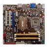
3.
When the fan and heatsink assembly is in place, connect the CPU fan cable
to the connector on the motherboard labeled CPU_FAN.
2.
Push down two fasteners at a time
in a diagonal sequence to secure
the heatsink and fan assembly in
place.
A
A
B
B
B
B
A
A
P5N7A-VM
P5N7A-VM CPU Fan Connector