Asus P5N7A-VM User Manual - Page 22
Motherboard layout, P5N7A-VM - motherboard pins
 |
UPC - 610839163564
View all Asus P5N7A-VM manuals
Add to My Manuals
Save this manual to your list of manuals |
Page 22 highlights
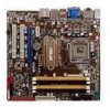
DDR2 DIMM_B1 (64 bit,240-pin module) DDR2 DIMM_B2 (64 bit,240-pin module) DDR2 DIMM_A1 (64 bit,240-pin module) DDR2 DIMM_A2 (64 bit,240-pin module) LPT EATXPWR FLOPPY 24.4cm (9.6in) 1.5.3 Motherboard layout 23.4cm (9.2in) KB/MS_USB56 SPDIFO_ HDMI_ DP_ ATX12V LGA775 PWR_FAN CPU_FAN Super I/O COM1 VGA_DVI F_ ESATA_ USB34 LAN1_USB12 CHA_FAN AUDIO 8Mb BIOS MCP7A-S CLRTC PCIEX1_1 CR2032 3V Lithium Cell CMOS Power P5N7A-VM RTL 8211CL PCIEX16 PRI_IDE ALC1200 SPDIF_OUT AAFP PCI1 PCI2 CD USB78 USB910 USB1112 CHASSIS SB_PWR SSAATTAA41 SSAATTAA52 JMB 368 SATA6 PANEL Refer to 1.10 Connectors for more information about rear panel connectors and internal connectors. 1-10 Chapter 1: Product Introduction
-
 1
1 -
2
-
3
-
4
-
5
-
6
-
7
-
8
-
9
-
10
-
11
-
12
-
13
-
14
-
15
-
16
-
 17
17 -
 18
18 -
 19
19 -
 20
20 -
 21
21 -
 22
22 -
 23
23 -
 24
24 -
 25
25 -
 26
26 -
 27
27 -
28
-
29
-
30
-
31
-
32
-
33
-
34
-
35
-
36
-
37
-
38
-
39
-
40
-
41
-
42
-
43
-
44
-
45
-
46
-
47
-
48
-
49
-
50
-
51
-
52
-
53
-
54
-
55
-
56
-
57
-
58
-
59
-
60
-
61
-
62
-
63
-
64
-
65
-
66
-
67
-
68
-
69
-
70
-
71
-
72
-
73
-
74
-
75
-
76
-
77
-
78
-
79
-
80
-
81
-
82
-
83
-
84
-
85
-
86
-
87
-
88
-
89
-
90
-
91
-
92
-
93
-
94
-
95
-
96
-
97
-
98
-
99
-
100
-
101
-
102
-
103
-
104
-
105
-
106
-
107
-
108
-
109
-
110
-
111
-
112
 |
 |

1-10
Chapter 1: Product Introduction
1.5.3
Motherboard layout
Refer to
1.10 Connectors
for more information about rear panel connectors
and internal connectors.
P5N7A-VM
23.4cm (9.2in)
SATA4
SATA1
SATA5
SATA6
SATA2
PWR_FAN
CHA_FAN
USB78
USB910
USB1112
AAFP
MCP7A-S
DDR2 DIMM_B1 (64 bit,240-pin module)
DDR2 DIMM_B2 (64 bit,240-pin module)
DDR2 DIMM_A1 (64 bit,240-pin module)
DDR2 DIMM_A2 (64 bit,240-pin module)
CR2032 3V
Lithium Cell
CMOS Power
PCI2
PCI1
PCIEX16
PCIEX1_1
CD
CHASSIS
ATX12V
FLOPPY
Super I/O
CPU_FAN
SB_PWR
CLRTC
SPDIF_OUT
RTL
8211CL
LGA775
PRI_IDE
8Mb
BIOS
LPT
KB/MS_USB56
VGA_DVI
SPDIFO_
HDMI_
DP_
F_
ESATA_
USB34
LAN1_USB12
AUDIO
COM1
PANEL
ALC1200
JMB
368
24.4cm (9.6in)
EATXPWR