Asus P6X58-E WS User Guide
Asus P6X58-E WS Manual
 |
View all Asus P6X58-E WS manuals
Add to My Manuals
Save this manual to your list of manuals |
Asus P6X58-E WS manual content summary:
- Asus P6X58-E WS | User Guide - Page 1
P6X58-E WS Motherboard - Asus P6X58-E WS | User Guide - Page 2
Product warranty or service will not be extended if: (1) the product is repaired, modified or altered, unless such repair, modification of alteration is authorized in writing by ASUS; or (2) the serial number of the product is defaced or missing. ASUS PROVIDES THIS MANUAL "AS IS" WITHOUT WARRANTY OF - Asus P6X58-E WS | User Guide - Page 3
guide x P6X58-E WS specifications summary xii Chapter 1: Product introduction 1.1 Welcome 1-1 1.2 Package contents 1-1 1.3 Special features 1-2 1.3.1 Product highlights 1-2 1.3.2 ASUS Unique features 1-3 Chapter 2: Hardware information 2.1 Before you proceed 2-1 2.2 Motherboard - Asus P6X58-E WS | User Guide - Page 4
Update utility 3-1 3.1.2 ASUS EZ Flash 2 utility 3-4 3.1.3 ASUS CrashFree BIOS 3 utility 3-5 3.2 BIOS setup program 3-6 3.2.1 BIOS menu screen 3-7 3.2.2 Menu bar 3-7 3.2.3 Navigation keys 3-7 3.2.4 Menu items 3-8 3.2.5 Sub-menu items 3-8 3.2.6 Configuration fields 3-8 3.2.7 Pop-up window - Asus P6X58-E WS | User Guide - Page 5
Contents 3.4.1 Ai Overclock Tuner [Auto 3-15 3.4.2 CPU Ratio Setting [Auto 3-15 3.4.3 Intel(R) SpeedStep(TM) Tech [Enabled 3-15 3.4.4 Intel(R) Turbo Mode Tech [Enabled 3-15 3.4.5 High TDP Turbo Mode [Auto 3-16 3.4.6 BCLK Frequency [XXX 3-16 3.4.7 PCIE Frequency [XXX 3-16 3.4.8 DRAM Frequency - Asus P6X58-E WS | User Guide - Page 6
4.3.6 Probe II 4-8 4.3.7 Sensor Recorder 4-9 4.3.9 Audio configurations 4-10 4.4 RAID configurations 4-12 4.4.1 RAID definitions 4-12 4.4.2 Installing Serial ATA hard disks 4-13 4.4.3 Setting the RAID item in BIOS 4-13 4.4.4 Intel® Matrix Storage Manager option ROM utility......... 4-14 vi - Asus P6X58-E WS | User Guide - Page 7
a RAID driver disk 4-22 4.5.1 Creating a RAID driver disk without entering the OS.... 4-22 4.5.2 Creating a RAID driver disk in Windows 4-22 4.5.3 Installing the RAID driver during Windows® OS installation 4-23 4.5.4 Using a USB floppy disk drive 4-24 Chapter 5: Multiple GPU technology support - Asus P6X58-E WS | User Guide - Page 8
operation. This equipment has been tested and found to comply with the accordance with manufacturer's instructions, may cause harmful technician for help. The use of shielded cables for connection of the monitor digital apparatus set out in ASUS website at http://csr.asus.com/english/ REACH.htm. viii - Asus P6X58-E WS | User Guide - Page 9
is set to service technician or your retailer. Operation safety • Before installing the motherboard and adding devices on it, carefully read all the manuals that came with the package problems with the product, contact a qualified service technician or your retailer. DO NOT throw the motherboard - Asus P6X58-E WS | User Guide - Page 10
tells how to change system settings through the BIOS Setup menus. Detailed descriptions of the BIOS parameters are also provided. • Chapter 4: Software support This chapter describes the contents of the support DVD that comes with the motherboard package and the software. • Chapter 5: Multiple - Asus P6X58-E WS | User Guide - Page 11
of the following symbols used throughout this manual. DANGER/WARNING: Information to prevent injury to yourself when trying to complete a task. CAUTION: Information to prevent damage to the components when trying to complete a task. IMPORTANT: Instructions that you MUST follow to complete - Asus P6X58-E WS | User Guide - Page 12
Due to Intel spec definition, DIMMs of DDR3-1800 or above are supported by specific CPU models only. *Please load X.M.P or D.O.C.P setting in BIOS for hyper DIMM (DDR3 1800MHz or above) support. **Refer to www.asus.com or this user manual for the Memory QVL (Qualified Vendors Lists) 1 x PCIe 2.0 x16 - Asus P6X58-E WS | User Guide - Page 13
P6X58-E WS specifications summary 1394 Audio ASUS Unique Features Workstation Unique Features BIOS Features Manageability Back Panel I/O Ports Form Factor VIA VT6315N supports 2 x 1394a ports Realtek ALC 889, 8 channels High Definition Audio CODEC - Multi-Streaming - Jack-Sensing - Front Panel - Asus P6X58-E WS | User Guide - Page 14
xiv - Asus P6X58-E WS | User Guide - Page 15
This chapter describes the motherboard features and the new technologies it supports. Chapter 1: 1Product introduction - Asus P6X58-E WS | User Guide - Page 16
Chapter summary 1 1.1 Welcome 1-1 1.2 Package contents 1-1 1.3 Special features 1-2 ASUS P6X58-E WS - Asus P6X58-E WS | User Guide - Page 17
devices on it, check the items in your package with the list below. 1.2 Package contents Check your motherboard package for the following items. Motherboard I/O modules Cables Accessories Application DVD Documentation ASUS P6X58-E WS 1 x USB 2.0 (2 ports) 2 x Serial ATA 6.0 Gb/s cables 2 x Serial - Asus P6X58-E WS | User Guide - Page 18
P�r�o�c�e��s�s�o�r��s��u���p��p���o���r�t This motherboard supports the latest Intel® Core™ i7 processors Extreme Edition / Core™ i7 processor / Xeon™ processors in LGA1366 package with integrated memory controller to support 3-channel (6 DIMMs) DDR3 memory. Supports Intel® QuickPath Interconnect - Asus P6X58-E WS | User Guide - Page 19
/s Support Experience the Future of Storage! Supporting next-generation Serial ATA (SATA) storage interface, this motherboard delivers ASUS 16+2 phase VRM design also ensure longer component life, minimum power loss, and help to reach the superior overclocking score ever than before. ASUS P6X58-E WS - Asus P6X58-E WS | User Guide - Page 20
uses lower CPU utilization, increasing throughput to achieve outstanding performance as well as better support for diverse operating systems.Besides,Intel® 82574L chipset has certification of VMware to support virtualization technology. G.P. Diagnosis card Bundled with P6X58-E WS motherboard (retail - Asus P6X58-E WS | User Guide - Page 21
which provides you with enhanced data protection via high-level encryption/decryption and ensures platform integrity. The TPM meets the Windows® Vista BitLocker™ Drive Encryption hardware requirement for a more secure working environment. The TPM module is purchased separately. ASUS P6X58-E WS 1-5 - Asus P6X58-E WS | User Guide - Page 22
computer components, update the BIOS or back up your favorite settings. ASUS Q-Design ASUS Q-Slot enhances your DIY experience that speeds up and simplifies the DIY process! ASUS Q-Shield The specially designed ASUS Q-Shield provides conductivity to best protect your motherboard against static - Asus P6X58-E WS | User Guide - Page 23
This chapter lists the hardware setup procedures that you have to perform when installing system components. It Chapter 2: includes description of the jumpers and connectors on the motherboard. 2 Hardware information - Asus P6X58-E WS | User Guide - Page 24
2-2 2.3 Central Processing Unit (CPU 2-5 2.4 System memory 2-11 2.5 Expansion slots 2-18 2.6 Onboard LEDs 2-22 2.7 Jumpers 2-23 2.8 Connectors 2-26 2.9 G.P. Diagnosis card installation 2-41 2.10 Starting up for the first time 2-43 2.11 Turning off the computer 2-44 ASUS P6X58-E WS - Asus P6X58-E WS | User Guide - Page 25
Before you proceed Take note of the following precautions before you install motherboard components or change any motherboard settings. • Unplug the power cord from the wall socket before touching any so may cause severe damage to the motherboard, peripherals, and/or components. ASUS P6X58-E WS 2-1 - Asus P6X58-E WS | User Guide - Page 26
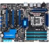
2.2 Motherboard overview 2.2.1 Motherboard layout Refer to 2.8 Connectors for more information about rear panel connectors and internal connectors. 2-2 Chapter 2: Hardware information - Asus P6X58-E WS | User Guide - Page 27
EZ_PLUG) 2. LGA1366 CPU Socket 3. CPU, chassis and power fan connectors (4-pin CPU_FAN, 4-pin CHA_FAN1-3, 3-pin PWR_FAN) 4. DDR3 DIMM slots 5. CPU / DRAM Bus / QPI DRAM overvoltage settings (3-pin 11 2-24 2-32 2-31 2-22 2-39 2-35 2-23 2-30 2-25 2-33 2-36 2-38 3-38 ASUS P6X58-E WS 2-3 - Asus P6X58-E WS | User Guide - Page 28
in the image below. 2.2.4 Screw holes Place nine (9) screws into the holes indicated by circles to secure the motherboard to the chassis. DO NOT overtighten the screws! Doing so can damage the motherboard. Place this side towards the rear of the chassis 2-4 Chapter 2: Hardware information - Asus P6X58-E WS | User Guide - Page 29
Authorization (RMA) requests only if the motherboard comes with the cap on the LGA1366 socket. • The product warranty does not cover damage to the socket contacts resulting from incorrect CPU installation/removal, or misplacement/loss/ incorrect removal of the PnP cap. ASUS P6X58-E WS 2-5 - Asus P6X58-E WS | User Guide - Page 30
Installing the CPU To install a CPU: 1. Locate the CPU socket on the motherboard. Before installing the CPU, make sure that the cam box is facing towards you and the load lever is on your left. 2. Press the load lever with your thumb (A), then move it to the left (B) until it is released from the - Asus P6X58-E WS | User Guide - Page 31
corner of the socket, and then fit the socket alignment key into the CPU notch. The CPU fits in only one correct orientation. DO NOT force the CPU into the socket to prevent bending the connectors on the socket and damaging the CPU! CPU notch Alignment key Gold triangle mark ASUS P6X58-E WS 2-7 - Asus P6X58-E WS | User Guide - Page 32
7. Apply several drops of thermal paste to the exposed area of the CPU that the heatsink will be in contact with, ensuring that it is spread in an even thin layer. Some heatsinks come with preapplied thermal paste. - Asus P6X58-E WS | User Guide - Page 33
match the holes on the motherboard. B 2. Push down two fasteners at a time in a diagonal sequence to secure the heatsink and fan assembly in place. A B A A B B A 1 1 Orient the heatsink and fan assembly such that the CPU fan cable is closest to the CPU fan connector. ASUS P6X58-E WS 2-9 - Asus P6X58-E WS | User Guide - Page 34
errors can occur if you fail to plug this connector. 2.3.3 Uninstalling the CPU heatsink and fan To uninstall the CPU heatsink and fan: 1. Disconnect the CPU fan cable from the connector on the motherboard. 2. Rotate each fastener counterclockwise. B 3. Pull up two fasteners at a time in - Asus P6X58-E WS | User Guide - Page 35
System memory 2.4.1 Overview The motherboard comes with six Double Data Rate 3 (DDR3) Dual Inline Memory Modules Intel CPU spec definition, the system will not boot if only one DIMM is installed in DIMM slot A2, B2, or C2. Follow the table above for recommended memory configuration. ASUS P6X58-E WS - Asus P6X58-E WS | User Guide - Page 36
-us. • This motherboard does not support DIMMs made up of 256 Mb (32MB) chips or less (Memory chip capacity counts in Megabit, 8 Megabit/Mb = 1 Megabyte/MB). • The default memory operation frequency is dependent on its SPD. Under the default state, some memory modules for overclocking may operate at - Asus P6X58-E WS | User Guide - Page 37
removing DIMMs or other system components. Failure to do so may cause severe damage to both the motherboard and the components. 1. Unlock a DIMM socket by pressing DIMM notch the retaining clip outward. 2. to unlock the DIMM. 2. Remove the DIMM from the 2 socket. 1 ASUS P6X58-E WS 2-13 - Asus P6X58-E WS | User Guide - Page 38
9CAASS37AZZ01D1 2048MB DS N/A Heat-Sink Package 9-9-9-24 V P6X58-E WS Motherboard Qualified Vendors Lists (QVL) DDR3-1866MHz capability Vendor Part No. DIMM socket Size SS/ DS Chip Brand Chip NO. Timing Dimm(Bios) Voltage support (Optional) A* B* C* D* KINGSTON KHX14900D3K3/3GX(XMP - Asus P6X58-E WS | User Guide - Page 39
P6X58-E WS Motherboard Qualified Vendors Lists (QVL) DDR3-1600MHz capability Vendor Part No. DIMM socket Size SS/ DS Chip Brand Chip NO. Timing Dimm(Bios) Voltage support (Optional) A* B* C* D* A-DATA AD31600E001GMU(XMP) 3072MB(Kit of 3) SS N/A Heat-Sink Package 8-8-8-24(1333-9-9-9-24) 1. - Asus P6X58-E WS | User Guide - Page 40
P6X58-E WS Motherboard Qualified Vendors Lists (QVL) DDR3-1333MHz capability Vendor Part No. Size SS/ Chip DS Brand Chip NO. Timing Dimm(Bios) Voltage DIMM socket support (Optional) A* B* C* D* A-DATA AD31333E002G0U 6144MB(Kit of 3) DS N/A Heat-Sink Package 7-7-7-20(1333-9-9-9-24) 1.65-1. - Asus P6X58-E WS | User Guide - Page 41
P6X58-E WS Motherboard Qualified Vendors Lists (QVL) DDR3-1066MHz capability Vendor Part No. Size SS/ Chip DS Brand Chip NO. DIMM socket support Timing Dimm(Bios) Voltage (Optional) A* B* C* D* CORSAIR CM3X1024-1066C7 1024MB DS N/A Heat-Sink Package 7 1.1 VV V Crucial CT12864BA1067. - Asus P6X58-E WS | User Guide - Page 42
and damage motherboard components. BIOS settings, if any. See Chapter 3 for information on BIOS setup. 2. Assign an IRQ to the card. Refer to the tables on the next page. 3. Install the software drivers for the expansion card. When using PCI cards on shared slots, ensure that the drivers support - Asus P6X58-E WS | User Guide - Page 43
9 Reserved IRQ assignments for this motherboard PCIEx16_1 PCIEx16_2 PCIEx16_3 PCIEx16_4 PCIEx16_5 PCIEx1_1 - - - shared - - - - - - - - - shared - - - shared - - - - - - - shared - - - - - - - - - - shared - - - - - - - - - - shared - ASUS P6X58-E WS 2-19 - Asus P6X58-E WS | User Guide - Page 44
slots Ensure to unplug the power cord before adding or removing expansion cards. Failure to do so may cause you physical injury and damage motherboard components. Slot No. Slot Description 1 PCIe 2.0 x16_1 slot (x16 mode) 2 PCIe 2.0 x16_2 slot (x8 mode) 3 PCIe 2.0 x16_3 slot (single at x16 or dual - Asus P6X58-E WS | User Guide - Page 45
recommend that you provide sufficient power when running CrossFireX™ or SLI™ mode. See page 2-31 for details. • Connect a chassis fan to the motherboard connector labeled CHA_FAN1/2/3 when using multiple graphics cards for better thermal environment. See page 2-29 for details. ASUS P6X58-E WS 2-21 - Asus P6X58-E WS | User Guide - Page 46
check key components (CPU, DRAM, VGA card, and HDD) in sequence during motherboard booting process. If problem is solved. This user-friendly design provides an intuitive way to locate the root problem within seconds. You may disable the POST State LEDs in BIOS. Refer to section 3.7.2 Boot Setting - Asus P6X58-E WS | User Guide - Page 47
the system so the BIOS can automatically reset parameter settings to default values. • Due to the chipset behavior, AC power off is required to enable C.P.R. function. You must turn off and on the power supply or unplug and plug the power cord before rebooting the system. ASUS P6X58-E WS 2-23 - Asus P6X58-E WS | User Guide - Page 48
the system to halt. For system failure due to the wrong setting of the OV_CPU jumper, shut down the computer and move the cap back to pins 1-2. • According to Intel CPU spec, DIMMs with voltage requirement over 1.65V may damage the CPU permanently. We recommend you install the DIMMs with the voltage - Asus P6X58-E WS | User Guide - Page 49
2-3 when using 4-pin fans. • If you use a 4-pin fan but set the jumper to pin 1-2, the fan you installed may not work. • If you use a 3-pin fan but set the jumper for a 4-pin fan, the fan control will not work and the fan you installed will always run at full speed. ASUS P6X58-E WS 2-25 - Asus P6X58-E WS | User Guide - Page 50
2.8 Connectors 2.8.1 Rear panel connectors Rear panel connectors 1. PS/2 mouse/keyboard combo port 2. Coaxial S/PDIF Out port 3. LAN2 (RJ-45) port* 4. IEEE 1394a port 5. LAN1 (RJ-45) port* 6. USB 2.0 ports 5 and 6 7. Optical S/PDIF Out port 8. USB 2.0 ports 3 and 4 9. USB 2.0 ports 1 and 2 10. USB - Asus P6X58-E WS | User Guide - Page 51
- 8-channel Line In Front Speaker Out Mic In Center/Subwoofer Rear Speaker Out Side Speaker Out 2.8.2 Audio I/O connections Audio I/O ports Connect to Headphone and Mic ASUS P6X58-E WS 2-27 - Asus P6X58-E WS | User Guide - Page 52
Connect to Stereo Speakers Connect to 2.1 channel Speakers Connect to 4.1 channel Speakers 2-28 Chapter 2: Hardware information - Asus P6X58-E WS | User Guide - Page 53
Connect to 5.1 channel Speakers Connect to 7.1 channel Speakers ASUS P6X58-E WS 2-29 - Asus P6X58-E WS | User Guide - Page 54
2.8.3 Internal connectors 1. TPM connector (20-1 pin TPM) This connector supports a Trusted Platform Module (TPM) system, which can securely store keys, digital certificates, passwords, and data. A TPM system also helps enhance network security, protects digital identities, - Asus P6X58-E WS | User Guide - Page 55
Configure SATA as item in the BIOS to [RAID]. See section 3.3.5 Storage Configuration for details. • Before creating a RAID set, refer to section 4.4 RAID configurations or the manual bundled in the motherboard support DVD. • You must install the Windows® XP Service Pack 3 before using Serial ATA - Asus P6X58-E WS | User Guide - Page 56
controller, you have to create a RAID driver disk using the motherboard support DVD and load the driver during OS installation. For 32/64bit Windows XP OS, load first the Marvell shared library driver, and then load Marvell 91xx SATA Controller Driver. For Windows Vista / Windows 7 OS, load only the - Asus P6X58-E WS | User Guide - Page 57
. Doing so will damage the motherboard! If your chassis suppots front panel USB ports, you can attach a front panel USB cable to these connectors. Connect the USB cable to ASUS Q-Connector (USB, blue) first, and then install the Q-Connector (USB) to the USB connector onboard. ASUS P6X58-E WS 2-33 - Asus P6X58-E WS | User Guide - Page 58
the fan connectors. Insufficient air flow inside the system may damage the motherboard components. These are not jumpers! Do not place jumper caps on the fan connectors! • Only the CPU-FAN and CHA-FAN 1-3 connectors support the ASUS Advanced Q-Fan feature. • If you install two or more VGA cards, we - Asus P6X58-E WS | User Guide - Page 59
labeled "Chassis Signal" and "Ground" are shorted with a jumper cap. Remove the jumper caps only when you intend to use the chassis intrusion detection feature. ASUS P6X58-E WS 2-35 - Asus P6X58-E WS | User Guide - Page 60
module to a slot opening at the back of the system chassis. Never connect a USB cable to the IEEE 1394a connector. Doing so will damage the motherboard! The IEEE 1394a module is purchased separately. 2-36 Chapter 2: Hardware information - Asus P6X58-E WS | User Guide - Page 61
Recommended Power Supply Wattage Calculator at http://support.asus.com/PowerSupplyCalculator/PSCalculator. aspx?SLanguage=en list PSU suggested list SilverStone ST1000 Seasonic SS-600HT Thermaltake W0083RE Thermaltake PUREPower-600AP Silverstone SST-ST75ZF EnerMAX EG701AX-VE (E)(24P) ASUS P6X58-E WS - Asus P6X58-E WS | User Guide - Page 62
If you are using ASUS HDMI-equipped graphics panel audio I/O module that supports either HD Audio or legacy motherboard's high-definition audio capability. • If you want to connect a high-definition front panel audio module to this connector, ensure that the Front Panel Type item in the BIOS is set - Asus P6X58-E WS | User Guide - Page 63
supports several BIOS settings. Pressing the power switch for more than four seconds while the system is ON turns the system OFF. • Reset button (2-pin RESET) This 2-pin connector is for the chassis-mounted reset button for system reboot without turning off the system power. ASUS P6X58-E WS - Asus P6X58-E WS | User Guide - Page 64
few steps. Refer to the instructions below to install the ASUS Q-Connector. 1. Connect the front panel cables to the ASUS Q-Connector. Refer to the labels 2. Install the ASUS Q-Connector to the system panel connector, making sure the orientation matches the labels on the motherboard. 3. The front - Asus P6X58-E WS | User Guide - Page 65
to avoid electrical shock hazard. 1. Locate the TPM connector (20-1 pin TPM) on the motherboard. 2. With the LEDs of the diagnosis card facing to the SATA ports, align the card connector with the TPM connector and press firmly until the card sits on the connector completely. ASUS P6X58-E WS 2-41 - Asus P6X58-E WS | User Guide - Page 66
D0 Initiate chip D1 Enable IO device for bootlock D2 Check and wake up system D3 Prepare system for memory detection and sizing D4 Memory test D5 Copy BIOS from ROM to RAM C0 Early CPU initiation C5 Wake up AP 0A Initiate KBC8042 0B Detect PS2 mouse 0C Detect PS2 keyboard 2A Initiate VGA - Asus P6X58-E WS | User Guide - Page 67
a power-on test. Check the jumper settings and connections or call your retailer for assistance. BIOS Beep Description One short beep VGA detected Quick boot set to disabled No keyboard down the key to enter the BIOS Setup. Follow the instructions in Chapter 3. ASUS P6X58-E WS 2-43 - Asus P6X58-E WS | User Guide - Page 68
system is ON, pressing the power switch for less than four seconds puts the system on sleep mode or soft-off mode, depending on the BIOS setting. Pressing the power switch for more than four seconds lets the system enter the soft-off mode regardless of the - Asus P6X58-E WS | User Guide - Page 69
This chapter tells how to change the system settings through the BIOS Setup menus. Detailed descriptions of the BIOS parameters are also provided. 3 BIOS setup - Asus P6X58-E WS | User Guide - Page 70
Chapter summary 3 3.1 Managing and updating your BIOS 3-1 3.2 BIOS setup program 3-6 3.3 Main menu 3-9 3.4 Ai Tweaker 3-14 3.5 Advanced menu 3-20 3.6 Power menu 3-28 3.7 Boot menu 3-32 3.8 Tools menu 3-36 3.9 Exit menu 3-39 ASUS P6X58-E WS - Asus P6X58-E WS | User Guide - Page 71
current BIOS file • Download the latest BIOS file from the Internet • Update the BIOS from an updated BIOS file • Update the BIOS directly from the Internet • View the BIOS version information This utility is available in the support DVD that comes with the motherboard package. ASUS Update requires - Asus P6X58-E WS | User Guide - Page 72
update the BIOS through the Internet 1. From the Windows® desktop, 2. click Start > Programs > ASUS > ASUSUpdate > ASUSUpdate. The ASUS Update main window appears. Select Update BIOS from the Internet from the drop‑down menu, and then click Next. 3. Select the ASUS FTP site 4. From the FTP - Asus P6X58-E WS | User Guide - Page 73
Select Update BIOS from a file from the dropdown menu, then click Next. P6X58WS.ROM P6X58WS Ensure to load the BIOS default settings to ensure system compatibility and stability. Select the Load Setup Defaults item under the Exit menu. Refer to section 3.9 Exit Menu for details. ASUS P6X58-E WS - Asus P6X58-E WS | User Guide - Page 74
. ASUSTek EZ Flash 2 BIOS ROM Utility V4.22 FLASH TYPE: MXIC 25L8005 Current ROM BOARD: P6X58-E WS VER: 0203 DATE: 02/10/2011 Update ROM BOARD: Unknown VER: Unknown DATE: Unknown PATH: A:\ A: Note [Enter] Select or Load [Tab] Switch [V] Drive Info [Up/Down/Home/End] Move [B] Backup - Asus P6X58-E WS | User Guide - Page 75
DVD or a USB flash drive that contains the BIOS file. The BIOS file in the motherboard support DVD may be older than the BIOS file published on the ASUS official website. If you want to use the newer BIOS file, download the file at support.asus.com and save it to a USB flash drive. Recovering - Asus P6X58-E WS | User Guide - Page 76
setup program This motherboard supports a programmable firmware chip that you can update using the provided utility described in section 3.1 Managing and updating your BIOS. Use the BIOS Setup program when you are installing a motherboard, reconfiguring your system, or prompted to "Run Setup." This - Asus P6X58-E WS | User Guide - Page 77
BIOS SETUP UTILITY Main Ai Tweaker Advanced Power Boot Tools Exit System Time System Date Language changing the overclocking settings For changing the advanced system settings For changing settings. The navigation keys may differ from one screen to another. ASUS P6X58-E WS 3-7 - Asus P6X58-E WS | User Guide - Page 78
, select it then press to display a list of options. Refer to 3.2.7 Pop-up window. 3.2.7 Pop-up window Select a menu item then press to display a pop-up window with the configuration options for that item. 3.2.8 Scroll bar BIOS SETUP UTILITY Main Ai Tweaker Advanced Power - Asus P6X58-E WS | User Guide - Page 79
System Time [xx:xx:xx] Allows you to set the system time. 3.3.2 System Date [Day xx/xx/xxxx] Allows you to set the system date. 3.3.3 Language [English] Allows you to select the display language for the BIOS setup screen. Configuration options Français] [Deutsch] [English] ASUS P6X58-E WS 3-9 - Asus P6X58-E WS | User Guide - Page 80
Exit v02.61 (C)Copyright 1985-2011, American Megatrends, Inc. The BIOS automatically detects the values opposite the dimmed items (Device, Vendor, device occurs multiple sectors at a time if the device supports multi-sector transfer feature. When set to [Disabled], the data transfer from and to - Asus P6X58-E WS | User Guide - Page 81
BIOS SETUP Sets the configuration for the Serial ATA connectors supported by the Southbridge chip. Configuration options: [IDE] [RAID RAID 0, RAID 1, RAID 5, RAID 10, or the Intel® Matrix Storage Technology configuration from the Serial ATA hard disk drives, set this item to [RAID]. ASUS P6X58-E WS - Asus P6X58-E WS | User Guide - Page 82
35] 3.3.6 AHCI Configuration This menu is the section for AHCI configuration. It appears only when you set the item Configure SATA as from the sub-menu of SATA Configuration to [AHCI]. Main AHCI Settings BIOS SETUP UTILITY AHCI CD/DVD Boot Time out [35] AHCI Port1 [Not Detected] AHCI Port2 [Not - Asus P6X58-E WS | User Guide - Page 83
General Help F10 Save and Exit ESC Exit v02.61 (C)Copyright 1985-2011, American Megatrends, Inc. Bios Information Displays the auto-detected BIOS information. Processor Displays the auto-detected CPU specification. System Memory Displays the auto-detected system memory. ASUS P6X58-E WS 3-13 - Asus P6X58-E WS | User Guide - Page 84
vary depending on the CPU and memory modules you install on the motherboard. BIOS SETUP UTILITY Main Ai Tweaker Advanced Power Boot Tools Exit Configure System Performance Settings Ai Overclock Tuner CPU Ratio Setting Intel(R) SpeedStep(TM) Tech Intel(R) Turbo Mode Tech High - Asus P6X58-E WS | User Guide - Page 85
the preset overclocking configuration options: Manual Auto D.O.C.P X.M.P. Allows you to individually set overclocking parameters. Loads the optimal settings for the system. Overclocks DRAM frequency by adjusting BCLK frequency. If you install memory module(s) supporting the eXtreme Memory Profile - Asus P6X58-E WS | User Guide - Page 86
you set the Ai Overclock Tuner item to [Manual], [D.O.C.P.] [Auto] Allows you to set the DDR3 operating frequency. Configuration the BCLK Frequency item settings. Selecting a very setting. 3.4.9 UCLK Frequency [Auto] Allows you to set settings. 3.4.10 QPI Link Data Rate [Auto] Allows you to set - Asus P6X58-E WS | User Guide - Page 87
22 for details. 3.4.15 IOH Voltage [Auto] Allows you to set the I/O Hub (IOH) voltage. The values range from 1.10V to 1.70V with a 0.02V interval. 3.4.16 IOH PCIE Voltage [Auto] Allows you to set the IOH PCIE voltage. The values range from 1.50V to 2.76V with a 0.02V interval. ASUS P6X58-E WS 3-17 - Asus P6X58-E WS | User Guide - Page 88
supported is [1.90V]. See CPU / DRAM Bus / QPI DRAM overvoltage setting on page 2-22 for details. • According to Intel CPU spec, DIMMs with voltage requirement over 1.65V may damage the CPU -2.50V 1.40625V- 1.70000V 1.32V-1.70V 1.76V-2.76V N/A N/A N/A N/A 1.66V-2.46V 3-18 Chapter 3: BIOS setup - Asus P6X58-E WS | User Guide - Page 89
the CPU Clock Skew item at the same time. Configuration options: [Auto] [Normal] [Delay 100ps]-[Delay 1500ps] 3.4.27 PCIE Spread Spectrum [Auto] Set to [Disabled] to enhance PCIE overclocking ability or [Auto] for EMI control. Configuration options: [Auto] [Disabled] [Enabled] ASUS P6X58-E WS 3-19 - Asus P6X58-E WS | User Guide - Page 90
. The items shown in this screen may be different due to the CPU you installed. BIOS SETUP UTILITY Advanced Configure advanced CPU settings Module Version:01.0D Manufacturer:Intel Brand String:Genuine Intel(R) CPU 000 @ 3.20GHz Frequency :3.20GHz BCLK Speed :133MHz Cache L1 :256 KB Cache - Asus P6X58-E WS | User Guide - Page 91
] For Windows XP or later OSes. [Legacy ordering] For Windows 2000 or earlier OSes. Intel(R) Virtualization Tech [Enabled] The Intel® Virtualization [All] Allows you to choose the number of CPU cores to activate in each processor package. Configuration options: [All] [1] [2] ASUS P6X58-E WS 3-21 - Asus P6X58-E WS | User Guide - Page 92
-supported CPU. Configuration options: [Disabled] [Enabled] C State package limit setting [Auto] This item appears only when you set the Intel(R) C-STATE Tech item to [Enabled]. We recommend that you set this item to [Auto] for BIOS to automatically detect the C-State mode supported by your CPU - Asus P6X58-E WS | User Guide - Page 93
BIOS SETUP UTILITY Advanced Intel VT-d Configuration Intel VT-d [Disabled] Intel Virtualization Technology for Directed I/O. Intel VT-d [Disabled] Allows you to enable or disable the Intel Virtualization Technology for Directed I/O. Configuration options: [Disabled] [Enabled] ASUS P6X58-E WS - Asus P6X58-E WS | User Guide - Page 94
BIOS SETUP UTILITY Advanced Onboard Devices Configuration High Definition Audio Front Panel Type Asmedia USB 3.0 Controller Battery Charging Support SSC Support Marvell SATA6G Controller Intel LAN1 Intel Panel Type [HD Audio] Allows you to set the front panel audio connector (AAFP) mode - Asus P6X58-E WS | User Guide - Page 95
/2 [Enabled] Allows you to enable or disable the onboard Intel LAN port1/2. Configuration options: [Enabled] [Disabled] LAN Boot ROM [Disabled] This item appears Controller [Enabled] [Enabled] Enables the onboard IEEE 1394a controller. [Disabled] Disables the controller. ASUS P6X58-E WS 3-25 - Asus P6X58-E WS | User Guide - Page 96
USB devices. Setting to [Auto] allows the system to detect the presence of USB devices at startup. If detected, the USB controller legacy mode is enabled. If no USB device is detected, the legacy USB support is disabled. Configuration options: [Disabled] [Enabled] [Auto] 3-26 Chapter 3: BIOS setup - Asus P6X58-E WS | User Guide - Page 97
] Plug And Play O/S [No] When set to [NO], BIOS configures all the devices in the system. When set to [YES] and if you install a Plug and Play operating system, the operating system configures the Plug and Play devices not required for boot. Configuration options: [No] [Yes] ASUS P6X58-E WS 3-27 - Asus P6X58-E WS | User Guide - Page 98
Determines whether to invoke VGA BIOS POST on S3/STR resume. Configuration options: [No] [Yes] 3.6.3 ACPI 2.0 Support [Disabled] Add additional support in the Advanced Programmable Interrupt Controller (APIC). When set to [Enabled], the ACPI APIC table pointer is included in the RSDT pointer list - Asus P6X58-E WS | User Guide - Page 99
you to disable the Power On by PS/2 keyboard function or set specific keys on the PS/2 keyboard to turn on the system. This feature requires an ATX power supply that provides at least 1A on the +5VSB lead. Configuration options: [Disabled] [Space Bar] [Ctrl-Esc] [Power Key] ASUS P6X58-E WS 3-29 - Asus P6X58-E WS | User Guide - Page 100
and Exit ESC Exit v02.61 (C)Copyright 1985-2011, American Megatrends, Inc. CPU Temperature [xxxºC/xxxºF] MB Temperature [xxxºC/xxxºF] The onboard hardware monitor automatically detects and displays the motherboard and CPU temperatures. Select [Ignored] if you do not wish to display the detected - Asus P6X58-E WS | User Guide - Page 101
is not connected to the motherboard, the field shows [N/A]. CPU Voltage, 3.3V Voltage, 5V Voltage, 12V Voltage The onboard hardware monitor automatically detects the voltage output through the onboard voltage regulators. Select [Ignored] if you do not want to detect this item. ASUS P6X58-E WS 3-31 - Asus P6X58-E WS | User Guide - Page 102
an item then press to display the sub-menu. BIOS SETUP UTILITY Main Ai Tweaker Advanced Power Boot Tools Exit Boot Settings Boot Device Priority Specifies the Boot Device Priority sequence. Boot Settings Configuration Security A virtual floppy disk drive (Floppy Drive - Asus P6X58-E WS | User Guide - Page 103
BIOS to skip some power on self tests (POST) while booting to decrease the time needed to boot the system. When set to [Disabled], BIOS When set to [Enabled], the system displays the message "Press DEL to run Setup" during POST. Configuration options: [Disabled] [Enabled] ASUS P6X58-E WS 3-33 - Asus P6X58-E WS | User Guide - Page 104
Security The Security menu items allow you to change the system security settings. Select an item then press to display the configuration options. BIOS SETUP UTILITY Boot Security Settings Supervisor Password : Not Installed User Password : Not Installed to change - Asus P6X58-E WS | User Guide - Page 105
to clear the user password. Password Check [Setup] When set to [Setup], BIOS checks for user password when accessing the Setup utility. When set to [Always], BIOS checks for user password both when accessing Setup and booting the system. Configuration options: [Setup] [Always] ASUS P6X58-E WS 3-35 - Asus P6X58-E WS | User Guide - Page 106
ASUSTek EZ Flash 2 BIOS ROM Utility V4.22 FLASH TYPE: MXIC 25L1605A Current ROM BOARD: P6X58-E-WS VER: 0203 DATE: 02/10/2011 Update ROM BOARD: Unknown VER: Unknown DATE: Unknown PATH: A:\ A: Note [Enter] Select or Load [Tab] Switch [V] Drive Info [Up/Down/Home/End] Move [B] Backup - Asus P6X58-E WS | User Guide - Page 107
to load the previous BIOS settings saved in the BIOS Flash. Press to load the file. Start O.C. Profile Allows you to run the utility to save and load CMOS. Press to run the utility. ASUSTek O.C. Profile Utility V2.22 Current CMOS BOARD: P6X58-E-WS VER: 0203 DATE: 02/10/2011 PATH - Asus P6X58-E WS | User Guide - Page 108
can support devices such as a USB flash disk with FAT 32/16 format and single partition only. • DO NOT shut down or reset the system while updating the BIOS to prevent the system boot failure! • We recommend that you update the BIOS file only coming from the same memory/CPU configuration and BIOS - Asus P6X58-E WS | User Guide - Page 109
you made changes to fields other than System Date, System Time, and Password, the BIOS asks for a confirmation before exiting. Discard window appears. Select Ok to load default values. Select Exit & Save Changes or make other changes before saving the values to the non-volatile RAM. ASUS P6X58-E WS - Asus P6X58-E WS | User Guide - Page 110
3-40 Chapter 3: BIOS setup - Asus P6X58-E WS | User Guide - Page 111
This chapter describes the contents of the support DVD that comes with the motherboard package and the software. 4 Software support - Asus P6X58-E WS | User Guide - Page 112
Chapter summary 4 4.1 Installing an operating system 4-1 4.2 Support DVD information 4-1 4.3 Software information 4-3 4.4 RAID configurations 4-12 4.5 Creating a RAID driver disk 4-22 ASUS P6X58-E WS - Asus P6X58-E WS | User Guide - Page 113
The Utilities menu shows the applications and other software that the motherboard supports. Click an item to install The Make Disk menu contains items to create the RAID/AHCI driver disk. The Manual menu contains the list of supplementary user manuals. Click an item to open the folder of the user - Asus P6X58-E WS | User Guide - Page 114
). Install the Adobe® Acrobat® Reader from the Utilities menu before opening the files. 1. Click the Manual tab. Click ASUS Motherboard Utility Guide from the manual list on the left. 2. The Manual folder of the support DVD appears. Doubleclick the folder of your selected software. 3. Some software - Asus P6X58-E WS | User Guide - Page 115
customize the interface settings Click to show the system information Click to update the motherboard BIOS Click to monitor sensors or CPU frequency Click to select a utility • The applications in the Tool menu vary with models. • The screeshots of AI Suite II in this user manual are for reference - Asus P6X58-E WS | User Guide - Page 116
main menu bar. Refer to the software manual in the support DVD or visit the ASUS website at www.asus.com for detailed software configuration. TurboV TurboV allows you to overclock the BCLK frequency, CPU voltage, IMC voltage, and DRAM Bus voltage in WIndows® environment and takes effect in real-time - Asus P6X58-E WS | User Guide - Page 117
value. Adjustment bar • Set the CPU Ratio Setting item in BIOS to [Auto] before using the CPU Ratio function in TurboV. Refer to Chapter 3 of your motherboard user manual for details. • The CPU Ratio bars show the status of the CPU cores, which vary with your CPU model. ASUS P6X58-E WS 4-5 - Asus P6X58-E WS | User Guide - Page 118
configuring settings like CPU frequency, GPU frequency, vCore Voltage, and Fan Control. Launching EPU After installing AI Suite II from the motherboard support DVD Refer to the software manual in the support DVD or visit the ASUS website at www.asus.com for detailed software configuration. 4-6 Chapter - Asus P6X58-E WS | User Guide - Page 119
Suite II from the motherboard support DVD, launch FAN the settings Click to discard the settings Fan setting • CPU fan profile under certain limitations. Refer to the software manual in the support DVD or visit the ASUS website at www.asus.com for detailed software configuration. ASUS P6X58-E WS - Asus P6X58-E WS | User Guide - Page 120
of any problem with these components. Probe II senses fan rotations, CPU temperature, and system voltages, among others. With this utility, you are assured that your computer is always at a healthy operating condition. Launching Probe II After installing AI Suite II from the motherboard support DVD - Asus P6X58-E WS | User Guide - Page 121
fan speed, as well as recording the changes. Launching Sensor Recorder After installing AI Suite II from the motherboard support DVD, click Tool > Sensor Recorder on the AI Suite II main menu bar to launch PC Probe II to zoom in/out the Y axis Click to zoom in/out the X axis ASUS P6X58-E WS 4-9 - Asus P6X58-E WS | User Guide - Page 122
installation wizard to install the Realtek® Audio Driver from the support DVD that came with the motherboard package. If the Realtek audio software is Windows® Vista™ Configuration option tabs Set default Minimize device button button Exit button Connector settings Control settings window - Asus P6X58-E WS | User Guide - Page 123
B. Realtek HD Audio Manager for Windows XP Configuration options Control settings window Exit button Minimize button Information button Refer to the software manual in the support DVD or visit the ASUS website at www.asus.com for detailed software configuration. ASUS P6X58-E WS 4-11 - Asus P6X58-E WS | User Guide - Page 124
configurations The motherboard supports the following SATA RAID solutions: • Intel® Matrix Storage Technology with RAID 0, RAID 1, RAID 10 and RAID 5 support. • Mavell® RAID utility with RAID 0 and RAID 1 support. • You must install Windows® XP Service Pack 3 or later versions before using Serial - Asus P6X58-E WS | User Guide - Page 125
Configure SATA as item to [RAID]. 4. Save your changes, and then exit the BIOS Setup. Refer to Chapter 3 for details on entering and navigating through the BIOS Setup. Due to chipset limitation, when set any of SATA ports to RAID mode, all SATA ports run at RAID mode together. ASUS P6X58-E WS 4-13 - Asus P6X58-E WS | User Guide - Page 126
Intel Corporation. All Rights Reserved. [ MAIN MENU ] 1. Create RAID Volume 3. Reset Disks to Non-RAID 2. Delete RAID Volume 4. Exit RAID move through the menus and select the menu options. The RAID BIOS setup screens shown in this section are for reference only and may not exactly - Asus P6X58-E WS | User Guide - Page 127
1 ST3160812AS 9LS0F4HL 149.0GB Non-RAID Disk 2 ST3160812AS 3LS0JYL8 149.0GB Non-RAID Disk 3 ST3160812AS 9LS0BJ5H 149.0GB Non-RAID Disk Select 2 to 6 disks to use in creating the volume. [↑↓]-Prev/Next [SPACE]-SelectDisk [ENTER]-Done ASUS P6X58-E WS 4-15 - Asus P6X58-E WS | User Guide - Page 128
. Deleting a RAID set Take caution when deleting a RAID set. You will lose all data on the hard disk drives when you delete a RAID set. To delete a RAID set 1. From the utility main menu, select 2. Delete RAID Volume and press . The following screen appears. 4-16 Chapter 4: Software support - Asus P6X58-E WS | User Guide - Page 129
"Volume0"? (Y/N): 3. Press to delete the RAID set and return to the utility main menu, or press to return to the DELETE VOLUME menu. Exiting the Intel® Matrix Storage Manager To exit the utility 1. From Press to exit or press to return to the utility main menu. ASUS P6X58-E WS 4-17 - Asus P6X58-E WS | User Guide - Page 130
The onboard Marvell SATA 6.0 Gb/s controller allows you to create a RAID 0 or RAID 1 array using two SATA hard disk drives. Refer to Chapter 2 of your motherboard user manual for the exact location of the Marvell SATA 6.0 Gb/s connector. To enter the Marvell utility, press + during - Asus P6X58-E WS | User Guide - Page 131
and press . The following warning message appears: Create Virtual Disk Do you want to create this virtual disk ? Yes No Press to create the RAID array, or press to cancel. The new RAID array appears under Virtual Disks, as shown in the image below. ASUS P6X58-E WS 4-19 - Asus P6X58-E WS | User Guide - Page 132
following warning message appears: Exit Do you want to exit from Marvell BIOS Setup? Yes No Press to save the RAID setting and exit the Marvell RAID utility. Delete an existing RAID Array 1. Select the RAID array to delete and press . Select Delete and press . Marvell - Asus P6X58-E WS | User Guide - Page 133
No Press to delete the Master Boot Record (MBR) from the selected RAID array. 3. Press . The following warning message appears: Exit Do you want to exit from Marvell BIOS Setup? Yes No Press to save the RAID setting and exit the Marvell RAID utility. ASUS P6X58-E WS 4-21 - Asus P6X58-E WS | User Guide - Page 134
>. 8. Follow the succeeding screen instructions to complete the process. 4.5.2 Creating a RAID driver disk in Windows® To create a RAID driver disk in Windows®: 1. Start Windows®. 2. Plug the USB floppy disk drive and insert a floppy disk. 3. Place the motherboard support DVD into the optical drive - Asus P6X58-E WS | User Guide - Page 135
driver for the corresponding OS version. Click OK. 4. Follow the succeeding screen instructions to complete the installation. Before loading the RAID driver from a USB flash drive, you have to use another computer to copy the RAID driver from the support DVD to the USB flash drive. ASUS P6X58-E WS - Asus P6X58-E WS | User Guide - Page 136
the RAID driver. 2. Right-click My Computer on the Windows® desktop or start menu, and then select Manage from the pop-up window. or displayed. 5. Browse the contents of the RAID driver disk to locate the file txtsetup.oem. 6. Double-click the file. A window appears, allowing you to select the - Asus P6X58-E WS | User Guide - Page 137
= "USB\VID_03EE&PID_6901", "usbstor" Add the same line to both sections. The VID and PID vary with different vendors. 10. Save and exit the file. ASUS P6X58-E WS 4-25 - Asus P6X58-E WS | User Guide - Page 138
4-26 Chapter 4: Software support - Asus P6X58-E WS | User Guide - Page 139
Multiple 5GPU This chapter describes how to install and configure multiple ATI® CrossFireX™ and NVIDIA® SLI™ graphics cards. technology support - Asus P6X58-E WS | User Guide - Page 140
Chapter summary 5 5.1 ATI® CrossFireX™ technology 5-1 5.2 NVIDIA® SLI™ technology 5-5 ASUS P6X58-E WS - Asus P6X58-E WS | User Guide - Page 141
Windows Vista, go to Control Panel > Programs and Features. For Windows 7, go to Control Panel > Programs > Uninstall a program. 3. Select your current graphics card driver/s. 4. For Windows XP, select Add/Remove. For Windows Vista, select Uninstall. 5. Turn off your computer. ASUS P6X58-E WS 5-1 - Asus P6X58-E WS | User Guide - Page 142
the two graphics card into the PCIEX16 slots. If your motherboard has more than two PCIEX16 slots, refer to Chapter 2 in this user manual for the locations of the PCIEX16 slots recommended for multi- or a DVI cable to the graphics card. Goldfingers 5-2 Chapter 5: Multiple GPU technology support - Asus P6X58-E WS | User Guide - Page 143
to the documentation that came with your graphics card package to install the device drivers. Ensure that your PCI Express graphics card driver supports the ATI® CrossFireX™ technology. Download the latest driver from the AMD website at www.amd.com. 5.1.5 Enabling the ATI® CrossFireX™ technology - Asus P6X58-E WS | User Guide - Page 144
Center window, click Graphics Settings > CrossFireX > Configure. 2. From the Graphics Adapter list, select the graphics card to act as the display GPU. 3. Select Enable CrossFireX. 1 4. Click Apply, and then click OK to exit the window. 2 3 4 5-4 Chapter 5: Multiple GPU technology support - Asus P6X58-E WS | User Guide - Page 145
motherboard supports card driver supports the NVIDIA SLI technology. Download the latest driver from supported by Windows® Vista™ operating system only. • Visit the NVIDIA zone website at http://www.nzone.com for the latest certified graphics card and supported 3D application list. ASUS P6X58-E WS - Asus P6X58-E WS | User Guide - Page 146
the two graphics card into the PCIEX16 slots. If your motherboard has more than two PCIEX16 slots, refer to Chapter 2 in this user manual for the locations of the PCIEX16 slots recommended for multi- cable to the graphics card. SLI bridge Goldfingers 5-6 Chapter 5: Multiple GPU technology support - Asus P6X58-E WS | User Guide - Page 147
the three graphics card into the PCIEX16 slots. If your motherboard has more than two PCIEX16 slots, refer to Chapter 2 in this user manual for the locations of the PCIEX16 slots recommended for multi-graphics Connect a VGA or a DVI cable to the graphics card. 3-Way SLI bridge ASUS P6X58-E WS 5-7 - Asus P6X58-E WS | User Guide - Page 148
package to install the device drivers. • Ensure that your PCI Express graphics card driver supports the NVIDIA® SLI™ technology. Download the latest driver from the NVIDIA website at www.nvidia.com. • If you are using a Triple SLI system, ensure to install the NVIDIA® 3-way SLI driver under Windows - Asus P6X58-E WS | User Guide - Page 149
B2. From the Personalization window, select Display Settings. B3. From the Display Settings dialog box, click Advanced Settings. B4. Select the NVIDIA GeForce tab, and then click Start the NVIDIA Control Panel. ASUS P6X58-E WS 5-9 - Asus P6X58-E WS | User Guide - Page 150
SLI rendered content. When done, click Apply. Enabling Triple SLI settings 1. From the NVIDIA Control Panel window, select Set SLI Configuration, and then click Enable 3-way NVIDIA SLI. When done, click Apply. 2. Select the 3D Settings tab and enable the Show SLI Visual Indicators item. When this - Asus P6X58-E WS | User Guide - Page 151
and Austria) Address Harkortstr. 21-23, 40880 Ratingen, Deutschland Telephone +49-2102-95990 Fax +49-2102-959911 Web site http://www.asus.de Online contact http://www.asus.de/sales Technical Support Telephone Support Fax Online support +49-1805-0109-23 +49-2102-9599-11 http - Asus P6X58-E WS | User Guide - Page 152
, TAIWAN R.O.C. Country: TAIWAN Authorized representative in Europe: ASUS COMPUTER GmbH Address, City: HARKORT STR. 21-23, 40880 RATINGEN Country: GERMANY declare the following apparatus: Product name : Motherboard Model name : P6X58-E WS conform with the essential requirements of the
-
 1
1 -
 2
2 -
 3
3 -
 4
4 -
 5
5 -
 6
6 -
 7
7 -
8
-
9
-
10
-
11
-
12
-
13
-
14
-
15
-
16
-
17
-
18
-
19
-
20
-
21
-
22
-
23
-
24
-
25
-
26
-
27
-
28
-
29
-
30
-
31
-
32
-
33
-
34
-
35
-
36
-
37
-
38
-
39
-
40
-
41
-
42
-
43
-
44
-
45
-
46
-
47
-
48
-
49
-
50
-
51
-
52
-
53
-
54
-
55
-
56
-
57
-
58
-
59
-
60
-
61
-
62
-
63
-
64
-
65
-
66
-
67
-
68
-
69
-
70
-
71
-
72
-
73
-
74
-
75
-
76
-
77
-
78
-
79
-
80
-
81
-
82
-
83
-
84
-
85
-
86
-
87
-
88
-
89
-
90
-
91
-
92
-
93
-
94
-
95
-
96
-
97
-
98
-
99
-
100
-
101
-
102
-
103
-
104
-
105
-
106
-
107
-
108
-
109
-
110
-
111
-
112
-
113
-
114
-
115
-
116
-
117
-
118
-
119
-
120
-
121
-
122
-
123
-
124
-
125
-
126
-
127
-
128
-
129
-
130
-
131
-
132
-
133
-
134
-
135
-
136
-
137
-
138
-
139
-
140
-
141
-
142
-
143
-
144
-
145
-
146
-
147
-
148
-
149
-
150
-
151
-
152
 |
 |

Motherboard
P6X58-E WS