Asus RS120-E3 User Guide - Page 59
Pin Frnt_fan1/2/3/4; Rear_fan1/2
 |
UPC - 610839630707
View all Asus RS120-E3 manuals
Add to My Manuals
Save this manual to your list of manuals |
Page 59 highlights
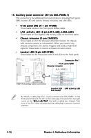
4. Hard disk activity LED connector (4-pin HDLED1) For some storage cards, such as SCSI card, with access signals for external LEDs, this connector allows the access signals to go through the front panel IDE_LED lead. ® P5MT-R HDLED1 1 NC ADD_IN_CARD_ACT# ADD_IN_CARD_ACT# NC P5MT-R Hard disk activity LED connector 5. System and device fan connectors (3-pin FRNT_FAN1/2/3/4; REAR_FAN1/2) The fan connectors support the system and device fans. Connect the backplane fan cable to the FRNT_FAN4 connector on the motherboard, making sure that the black wire of each cable matches the ground pin of the connector. These are not jumpers! Do not place jumper caps on the fan connectors! FRNT_FAN1 FRNT_FAN2 ® P5MT-R FRNT_FAN3 FRNT_FAN4 GND +12V Rotation GND +12V Rotation GND +12V Rotation GND +12V Rotation P5MT-R Fan connectors REAR_FAN1 GND +12V Rotation REAR_FAN2 GND +12V Rotation ASUS RS120-E3/PA4 4-11
-
 1
1 -
2
-
3
-
4
-
5
-
6
-
7
-
8
-
9
-
10
-
11
-
12
-
13
-
14
-
15
-
16
-
17
-
18
-
19
-
20
-
21
-
22
-
23
-
24
-
25
-
26
-
27
-
28
-
29
-
30
-
31
-
32
-
33
-
34
-
35
-
36
-
37
-
38
-
39
-
40
-
41
-
42
-
43
-
44
-
45
-
46
-
47
-
48
-
49
-
50
-
51
-
52
-
53
-
 54
54 -
 55
55 -
 56
56 -
 57
57 -
 58
58 -
 59
59 -
 60
60 -
 61
61 -
 62
62 -
 63
63 -
 64
64 -
65
-
66
-
67
-
68
-
69
-
70
-
71
-
72
-
73
-
74
-
75
-
76
-
77
-
78
-
79
-
80
-
81
-
82
-
83
-
84
-
85
-
86
-
87
-
88
-
89
-
90
-
91
-
92
-
93
-
94
-
95
-
96
-
97
-
98
-
99
-
100
-
101
-
102
-
103
-
104
-
105
-
106
-
107
-
108
-
109
-
110
-
111
-
112
-
113
-
114
-
115
-
116
-
117
-
118
-
119
-
120
-
121
-
122
-
123
-
124
-
125
-
126
-
127
-
128
-
129
-
130
-
131
-
132
-
133
-
134
-
135
-
136
-
137
-
138
-
139
-
140
-
141
-
142
-
143
-
144
-
145
-
146
-
147
-
148
-
149
-
150
-
151
-
152
-
153
-
154
-
155
-
156
-
157
-
158
-
159
-
160
-
161
-
162
-
163
-
164
-
165
-
166
-
167
-
168
-
169
-
170
-
171
-
172
 |
 |
