Asus RS160-E4 User Guide
Asus RS160-E4 - 0 MB RAM Manual
 |
UPC - 610839648061
View all Asus RS160-E4 manuals
Add to My Manuals
Save this manual to your list of manuals |
Asus RS160-E4 manual content summary:
- Asus RS160-E4 | User Guide - Page 1
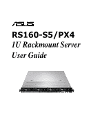
RS160-S5/PX4 1U Rackmount Server User Guide - Asus RS160-E4 | User Guide - Page 2
, and should not be construed as a commitment by ASUS. ASUS assumes no responsibility or liability for any errors or inaccuracies that may appear in this manual, including the products and software described in it. Product warranty or service will not be extended if: (1) the product is repaired - Asus RS160-E4 | User Guide - Page 3
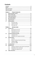
Contents Contents...iii Notices...vii Safety information viii About this guide ix Chapter 1: Product introduction 1.1 System package contents 1-2 1.2 Serial number label 1-2 1.3 System specifications 1-3 1.4 Front panel features 1-5 1.5 Rear panel features 1-5 1.6 Internal features 1-6 1.7 - Asus RS160-E4 | User Guide - Page 4
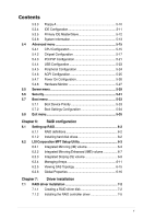
4-8 Chapter 5: BIOS setup 5.1 Managing and updating your BIOS 5-2 5.1.1 Creating a bootable floppy disk 5-2 5.1.2 AFUDOS utility 5-3 5.1.3 ASUS CrashFree BIOS 3 utility 5-6 5.2 BIOS setup program 5-7 5.2.1 BIOS menu screen 5-8 5.2.2 Menu bar 5-8 5.2.3 Navigation keys 5-8 5.2.4 Menu - Asus RS160-E4 | User Guide - Page 5
Contents 5.3.3 Floppy A 5-10 5.3.4 IDE Configuration 5-11 5.3.5 Primary IDE Master/Slave 5-12 5.3.6 System Information 5-13 5.4 Advanced menu 5-15 5.4.1 CPU Configuration 5-15 5.4.2 Chipset Configuration 5-17 5.4.3 PCI/PnP Configuration 5-21 5.4.4 USB Configuration 5-23 5.4.5 Peripheral - Asus RS160-E4 | User Guide - Page 6
7-12 7.3 LAN driver installation 7-15 7.4 VGA driver installation 7-19 7.5 Management applications and utilities installation 7-21 7.5.1 Running the support CD 7-21 7.5.2 Drivers menu 7-21 7.5.3 Management Software menu 7-22 7.5.4 Utilities menu 7-22 7.5.5 Contact information 7-22 vi - Asus RS160-E4 | User Guide - Page 7
. This equipment generates, uses and can radiate radio frequency energy and, if not installed and used in accordance with manufacturer's instructions, may cause harmful interference to radio communications. However, there is no guarantee that interference will not occur in a particular installation - Asus RS160-E4 | User Guide - Page 8
to fix it by yourself. Contact a qualified service technician or your dealer. Operation Safety • Any operating the server, carefully read all the manuals included with the server package. • Before used batteries according to the manufacturer's instructions. CD-ROM Drive Safety Warning CLASS - Asus RS160-E4 | User Guide - Page 9
basic knowledge of configuring a server. Contents This guide contains the following parts: 1. Chapter 1: Product how to install optional components into the barebone server. 4. Chapter 4: Motherboard information This This chapter provides instructions for installing the necessary drivers for different - Asus RS160-E4 | User Guide - Page 10
for product and software updates. 1. ASUS Server Web-based Management (ASWM) user guide This manual tells how to set up and use the proprietary ASUS server management utility. 2. ASUS websites The ASUS websites worldwide provide updated information for all ASUS hardware and software products. Refer - Asus RS160-E4 | User Guide - Page 11
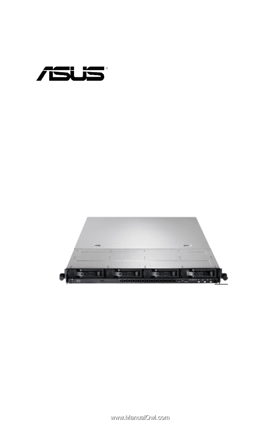
Product introduction Chapter 1 This chapter describes the general features of the chassis kit. It includes sections on front panel and rear panel specifications. ASUS RS160-S5/PX4 1- - Asus RS160-E4 | User Guide - Page 12
fans 1 x Air Duct Accessories 2 x CPU Heatsinks 1 x RS160-S5/PX4 User's Guide 1 x ASUS ASWM 2.0 User's Guide 1 x RS160-S5/PX4 Support CD (including ASWM*) 1 x Bag of Screws 1 x product, ASUS Technical Support team members can then offer a quicker and satisfying solution to your problems. RS160-S5 - Asus RS160-E4 | User Guide - Page 13
server featuring the ASUS DSEB-DG/SAS server board. The server supports Intel® LGA771 Xeon® E5400 / E5300 / E5200 / E5100 Series processors with EM64T technology, plus other latest technologies through the chipsets onboard. Model Name Processor / System Bus Core Logic RS160-E4/SI 2 x Socket LGA771 - Asus RS160-E4 | User Guide - Page 14
DD) Net Weight Kg (CPU, DRAM & HDD not inclu ded) Power Supply Environment CA® eTrust™ 7.1 anti-virus software (Optional) ASMB3-SOL PLUS (Optional) ASUS ASWM 2.0 686mm x 444mm x 43.4mm 15 Kg 650W Single Power Supply Operation temperature: 10°C ~ 35°C Non operation temperature: -40°C ~ 70°C Non - Asus RS160-E4 | User Guide - Page 15
1.4 Front panel features The barebone server displays a simple yet stylish front panel with easily accessible features. The power and reset buttons, LED LAN port 1 / 2 VGA port Serial port USB ports PS/2 keyboard port PS/2 mouse port Power supply fan Power cord connector ASUS RS160-S5/PX4 1-5 - Asus RS160-E4 | User Guide - Page 16
Internal features The barebone server includes the basic components as shown. 2 1 4 3 5 555 5 5 6 7 8 12 9 10 11 1. PCI Express x16 riser card bracket 2. Power fans 3. ASUS DSEB-DG/SAS/ RS160-S5 server board 4. Power supply 5. System fans 6. SATA II /SAS backplane (ASUS BP4LX-R10) 7. Hot - Asus RS160-E4 | User Guide - Page 17
GREEN Linked BLINKING Data activity SPEED LED ACT/LINK LED SPEED LED Status Description OFF 10 Mbps connection ORANGE 100 Mbps connection GREEN 1 Gbps connection ASUS RS160-S5/PX4 1-7 - Asus RS160-E4 | User Guide - Page 18
1.7.3 HDD status LED HDD Status LED HDD Activity LED SATAII/SAS HDD LED Description GREEN ON SATAII/SAS HDD power ON RED ON SATAII/SAS HDD not present HDD Status LED RED 1. HDD has failed and should be Blinking swapped immediately (slow blinking, (SAS 2 times/sec) only) 2. RAID - Asus RS160-E4 | User Guide - Page 19
Hardware setup Chapter 2 This chapter lists the hardware setup procedures that you have to perform when installing or removing system components. ASUS RS160-S5/PX4 2- - Asus RS160-E4 | User Guide - Page 20
2.1 Chassis cover 2.1.1 Removing the front cover 1. Use a Phillips screwdriver to remove the screw on each front end of the front cover. 2. Loosen the two thumbscrews on the rear panel to release the rear cover from the chassis. Thumbscrews 3. Firmly hold the front cover and slide it toward the - Asus RS160-E4 | User Guide - Page 21
the front cover. 7. Disconnect the SATA cable and the power plug from the connectors on the back of the drive. 8. Leave the front cover aside. ASUS RS160-S5/PX4 2-3 - Asus RS160-E4 | User Guide - Page 22
2.1.2 Removing the rear cover 1. Loosen the two thumbscrews on the rear panel to release the top cover from the chassis. Thumbscrews 2. Firmly hold the cover and slide it toward the rear panel for about half an inch until it is disengaged from the chassis. 3. Lift the cover from the chassis. 1/2 - Asus RS160-E4 | User Guide - Page 23
the chassis. Grooves 3. Slide the cover toward the front until it snaps in place. 4. Tighten the thumbscrews on the rear to secure the cover. Thumbscrews ASUS RS160-S5/PX4 2-5 - Asus RS160-E4 | User Guide - Page 24
come with installation instructions for the CPU and heatsink. If the instructions in this section the cap after installing the motherboard. ASUS will process Return Merchandise Authorization (RMA) on the motherboard. CPU1 CPU2 ® DSEB-DG/SAS/RS160-S5 CPU LGA771 Before installing the CPU, make sure - Asus RS160-E4 | User Guide - Page 25
triangle is on the bottom-left corner of the socket. The socket alignment key should fit into the CPU notch. Alignment key Gold triangle mark ASUS RS160-S5/PX4 A 2-7 - Asus RS160-E4 | User Guide - Page 26
The CPU fits in only one correct orientation. DO NOT force the CPU into the socket to prevent bending the connectors on the socket and damaging the CPU! A 6. Close the load plate (A), then push the load lever (B) until it snaps into the retention tab. B 2-8 Chapter 2: Hardware setup - Asus RS160-E4 | User Guide - Page 27
completely secure the heatsink. To install the airduct: 1. Position the airduct on top of the heatsink. 2. Carefully lower the airduct until it fits in place. ASUS RS160-S5/PX4 2-9 - Asus RS160-E4 | User Guide - Page 28
motherboard features eight fully-buffered DIMM (FB-DIMM) sockets to support 240-pin FB-DIMM modules. You can purchase extra FB- : 128 Pins DIMM_31 DIMM_30 DIMM_21 ® DIMM_20 DIMM_11 DIMM_10 DIMM_01 DIMM_00 DSEB-DG/SAS/RS160-S5 240-pin FB-DIMM sockets 112 Pins Rank population DIMM 31 DIMM 30 DIMM - Asus RS160-E4 | User Guide - Page 29
, DIMM_11) (DIMM_21, DIMM_31) Memory architecture single channel dual-channel Quadri-channel Quadri-channel Quadri-channel DIMMs in pair means two DIMMs with the same configuration. ASUS RS160-S5/PX4 2-11 - Asus RS160-E4 | User Guide - Page 30
2.3.2 Memory mirroring and sparing technology The Intel® 5400 chipset supports the memory mirroring and sparing technology. Refer to the below sections: Memory Mirroring: When enabling memory mirroring function in the BIOS setting (please refer the - Asus RS160-E4 | User Guide - Page 31
sized rank to a larger sized one. • A DIMM can contain only one or two ranks. To support sparing function, a DIMM channel should contain at least two ranks. • When sparing function is enabled, the *2 Ranks) Rank 0 Rank 1 (1024 MB) (1024 MB) 1024 MB 1024 MB 2048 MB ASUS RS160-S5/PX4 2-13 - Asus RS160-E4 | User Guide - Page 32
Two DIMM per channel (two ranks) Sparing Memory space Branch0 Sparing Memory space Total Memory Channel 0 DIMM_00 (512MB*2 Ranks) Rank 0 Rank 1 (512 MB) (512 MB) Channel 1 DIMM_10 (512MB*2 Ranks) Rank 0 Rank 1 (512 MB) (512 MB) 1024 MB DIMM_01 (1024MB*2 Ranks) Rank 0 Rank 1 (1024 - Asus RS160-E4 | User Guide - Page 33
remove a DIMM: 1. Simultaneously press the retaining clips outward to unlock the DIMM. 1 Support the DIMM lightly with your fingers when pressing the retaining clips. The DIMM might get damaged when it flips out with extra force. 2. Remove the DIMM from the socket. 2 1 ASUS RS160-S5/PX4 2-15 - Asus RS160-E4 | User Guide - Page 34
2.4 Hard disk drives The system supports four hot-swap SATAII/SAS hard disk drives. The hard disk drive installed on the drive tray connects to the motherboard SATAII/SAS ports via - Asus RS160-E4 | User Guide - Page 35
cables to the connectors on the SATAII/ SAS backplane. Refer to section 2.7 SATAII/SAS backplane cabling for information on the SATAII/SAS backplane cable connections. ASUS RS160-S5/PX4 2-17 - Asus RS160-E4 | User Guide - Page 36
2.5 Expansion slot 2.5.1 Installing an expansion card to the riser card bracket The barebone server comes with a riser card bracket. You need to remove the bracket if you want to install PCI Express x16 expansion cards. To install a PCI - Asus RS160-E4 | User Guide - Page 37
slot on the motherboard. 3. Press the riser card bracket until the golden connectors completely fit the slot and the bracket aligns with the rear panel. ASUS RS160-S5/PX4 2-19 - Asus RS160-E4 | User Guide - Page 38
4. Secure the riser card bracket with a screw. 5. Connect the cable(s) to the card, if applicable. 2-20 Chapter 2: Hardware setup - Asus RS160-E4 | User Guide - Page 39
Mouse Port 13 8 Numeric Data Processor 14* 9 Primary IDE Channel 15* 10 Secondary IDE Channel * These IRQs are usually available for ISA or PCI devices. ASUS RS160-S5/PX4 2-21 - Asus RS160-E4 | User Guide - Page 40
2.6 Cable connections 8 2 6 7 1 4 54 42 3 Pre-connected system cables 1. 24-pin SSI power connector (from power supply to motherboard) 2. 4-pin/8-pin SSI power connector (from power supply to motherboard) 3. SAS backplane power connector (from power supply) 4. System fan connectors (from - Asus RS160-E4 | User Guide - Page 41
MB Connects the SATA cable from SAS1 port on the MB Connects the SATA cable from SAS1 port on the MB Connect the SAS HDDs ASUS RS160-S5/PX4 2-23 - Asus RS160-E4 | User Guide - Page 42
2.8 Removable components You may need to remove previously installed system components when installing or removing system devices, or when you need to replace defective components. This section tells how to remove the following components: 1. System fans 2. Power supply module 3. Optical drive 4. - Asus RS160-E4 | User Guide - Page 43
system fans. To uninstall the side system fans 1. Disconnect the system fan cable from the connector on the motherboard. 2. Lift the fan, then set aside. ASUS RS160-S5/PX4 2-25 - Asus RS160-E4 | User Guide - Page 44
To reinstall the center system fans 1. Insert the fan to the fan cage. The airflow directional arrow on the fan side should point towards the system rear panel. 2. Connect the system fan cable to the fan connector on the motherboard. To reinstall the side system fan 1. Insert the fan to the fan cage - Asus RS160-E4 | User Guide - Page 45
secure the power supply from the chassis. 4. Slide the power supply forward for about half an inch, then carefully lift it out from the chassis. ASUS RS160-S5/PX4 2-27 - Asus RS160-E4 | User Guide - Page 46
section 2.1.1 Removing the front cover to remove the front cover from the barebone server. 2. Use a Phillips screwdriver (cross) to remove the three screws to its metal bracket. To reinstall the optical drive, follow the instructions in the previous chapter in a reverse order. When installing a new - Asus RS160-E4 | User Guide - Page 47
the CPU and heatsink, riser card bracket, and DDR DIMMs. Refer to the corresponding sections for instructions on removing these components. 3. Use a Philips (cross) screwdriver to remove the screws that secure . ® 4. Carefully lift the motherboard out of the chassis as shown. ASUS RS160-S5/PX4 2-29 - Asus RS160-E4 | User Guide - Page 48
To reinstall the motherboard: 1. Firmly hold the motherboard by the sides and insert it into the chassis as shown. 2. Carefully adjust the motherboard until the rear panel ports fit in place. 3. Use a Phillips (cross) screwdriver to secure the motherboard with nine (9) screws in the holes as shown - Asus RS160-E4 | User Guide - Page 49
Installation options Chapter 3 This chapter describes how to install the optional components and devices into the barebone server. ASUS RS160-S5/PX4 2- - Asus RS160-E4 | User Guide - Page 50
3.1 Rackmount rail kit items If you have the rackmount rail kit, it contains two pairs of rails (one pair for each side of the barebone system), and eight (8) pairs of nut-and-bolt type screws. Nuts Bolts Left pair Right pair 3.2 Rack rails assembly To assemble the rack rails: 1. Determine - Asus RS160-E4 | User Guide - Page 51
to the rack: 1. Select one unit of space (1U) on the rack where you wish to install the barebone server. 2. Remove the screws from the 1U space on the rack front. 3. Align the front end holes of the second rail pair. When properly installed, the rack rails appear as shown. ASUS RS160-S5/PX4 3-3 - Asus RS160-E4 | User Guide - Page 52
3.4 Rackmounting the server To mount the server to the rack: 1. Firmly hold the server on both sides and insert the rear panel side to the front end of the rack rail, then carefully push the server all the way to the back until the front panel fits the front end of the rack, and the rack screws on - Asus RS160-E4 | User Guide - Page 53
Motherboard info Chapter 4 This chapter includes the motherboard layout, and brief descriptions of the jumpers and internal connectors. ASUS RS160-S5/PX4 - Asus RS160-E4 | User Guide - Page 54
SATA3 SATA4 SATA5 SATA6 LAN_EN3 Intel 82573L LAN_EN4 Super I/O 8Mb FWH LPC1 RECOVERY1 SB_PWR1 AUX_PANEL1 SASLED1 LED1 SAS_EN1 PCIE3 DSEB-DG/SAS/RS160-S5 PCIE4 LSI SAS1068 COM2 PCIX5 PCIX6 PANEL1 FLOPPY1 USB34 Intel® 6321ESB BUZZER1 CLRTC1 XGI Volari Z9s HDLED1 VGA_EN1 CR2032 3V - Asus RS160-E4 | User Guide - Page 55
) 12. System panel connector (20-1 pin PANEL1) 13. Auxiliary panel connector (20-pin AUX_PANEL1) Page 4-8 4-8 4-9 4-10 4-11 4-11 4-12 4-12 4-13 4-13 4-14 4-15 4-16 ASUS RS160-S5/PX4 4-3 - Asus RS160-E4 | User Guide - Page 56
cell battery powers the RAM data in CMOS, which include system setup information such as system passwords. ® CLRTC1 DSEB-DG Series/SAS/RS160-S5 To erasCeletahreRRTTCCRRAAMM: 2 1 Normal (Default) 3 2 Clear CMOS 1. Turn OFF the computer and unplug the power cord. 2. Move the jumper cap from pins - Asus RS160-E4 | User Guide - Page 57
and the onboard Intel® 82573L Gigabit LAN controllers. Set to pins 1-2 to activate the Gigabit LAN feature. ® DSEB-DG/SAS/RS160-S5 LAN setting LAN_EN1 12 23 Enable Disable (Default) LAN_EN3 2 1 Enable (Default) 3 2 Disable LAN_EN4 2 1 Enable (Default) 3 2 Disable ASUS RS160-S5/PX4 4-5 - Asus RS160-E4 | User Guide - Page 58
fans and FB-DIMM fans. Set to pins 1-2 for 4-pin fans or pins 2-3 for 3-pin fans. FAN_SET1 FAN_SET2 ® 12 23 Balanced (Default) DSEB-DG/SAS/RS160-S5 FAN setting DC FAN • If you use a 4-pin fan but set the jumper to pin 2-3, the fan you installed may not work. • If you - Asus RS160-E4 | User Guide - Page 59
BIOS. 4. Shut down the system. 5. Set the jumper back to pins 1-2. 6. Turn on the system. ® RECOVERY1 12 23 Normal BIOS Recovery (Default) DSEB-DG/SAS/RS160-S5 BIOS recovery setting ASUS RS160-S5/PX4 4-7 - Asus RS160-E4 | User Guide - Page 60
when using a FDD cable with a covered Pin 5. ® FLOPPY1 PIN1 NOTE: Orient the red markings on the floppy ribbon cable to PIN 1. DSEB-DG/SAS/RS160-S5 Floppy disk drive connector 2. Serial ATA connectors (7-pin SATA1, SATA2, SATA3, SATA4, SATA5, SATA6 ) These connectors are for the Serial ATA signal - Asus RS160-E4 | User Guide - Page 61
insertion when you connect the IDE cable. • Use the 80-conductor IDE cable for Ultra DMA 100/66 IDE devices. ® PRI_IDE1 PIN1 DSEB-DG/SAS/RS160-S5 IDE connector ASUS RS160-S5/PX4 4-9 - Asus RS160-E4 | User Guide - Page 62
comes with two Serial Attached SCSI (SAS) connectors, the next-generation storage technology that supports both Series SCSI and Serial ATA (SATA). Each connector supports one device. ® DSEB-DG/SAS/RS160-S5 MINI SAS connectors To connect the SAS cable: To disconnect the SAS cable: Plug - Asus RS160-E4 | User Guide - Page 63
LED port indicator that shows the SAS HDD status. SASLED1 ® PIN1 DSEB-DG/SAS/RS160-S5 SASLED connector 6. Hard disk activity LED connector (4-pin HDLED1) This connector is used PIN1 HDLED1 DSEB-DG/SAS/RS160-S5 storage card activity LED connector NC ADD_IN_CARDADD_IN_CARDNC ASUS RS160-S5/PX4 4-11 - Asus RS160-E4 | User Guide - Page 64
at the back of the system chassis. This USB connector complies with USB 2.0 specification that supports up to 480 Mbps connection speed. Power USB PortB(-) USB PortB(+) GND NC ® USB34 PIN1 DSEB-DG/SAS/RS160-S5 USB connector Power USB PortA(-) USB PortA(+) GND The USB port module is purchased - Asus RS160-E4 | User Guide - Page 65
separately. 10. Power supply SMBus connector (5-pin PSUSMB1) This connector is for the power supply SMB cable, if your power supply supports the SMBus function. PSUSMB1 ® DSEB-DG/SAS/RS160-S5 Power supply SMBus connector I2C_7_CLK# I2C_7_DATA# NC GND +3.3V Remote Sense ASUS RS160-S5/PX4 4-13 - Asus RS160-E4 | User Guide - Page 66
GND GND +3 Volts -12 Volts Ground PSON# Ground Ground Ground -5 Volts +5 Volts +5 Volts +5 Volts Ground 12V1 12V1 12V2 12V2 ® ATX12V2 4-pin DSEB-DG/SAS/RS160-S5 ATX power connectors GND +12V DC GND +12V DC • For a fully configured system, we recommend that you use an SSI 12 V-compliant power - Asus RS160-E4 | User Guide - Page 67
supports several chassis-mounted functions. The system panel connector is color-coded for easy connection. POWERLED+ NC POWERLEDMLED+ MLEDNC +5V GND GND SPKROUT IDELED+ IDELEDNMIBTN# GND POWERBTN# GND NC RESETBTN# GND ® PANEL1 PIN1 DSEB-DG/SAS/RS160 off the system power. ASUS RS160-S5/PX4 4-15 - Asus RS160-E4 | User Guide - Page 68
# +5VSB LAN1_LINK LAN1_ACT LAN2_ACT LAN2_LINK ® AUX_PANEL1 PIN1 +5VSB CASEOPEN GND LOCATORLED1+ LOCATORLED1- LOCATORBTN# GND LOCATORLED2LOCATORLED2+ DSEB-DG/SAS/RS160-S5 Auxiliary panel connector 3 454 1. Front panel SMB (6-1 pin FPSMB) These leads connect the front panel SMBus cable. 2. LAN - Asus RS160-E4 | User Guide - Page 69
Chapter 5 This chapter tells how to change the system settings through the BIOS Setup menus. Detailed descriptions of the BIOS parameters are also provided. BIOS setup ASUS RS160-S5/PX4 5-1 - Asus RS160-E4 | User Guide - Page 70
manage and update the motherboard Basic Input/Output System (BIOS) setup: 1. AFUDOS utility (Updates the BIOS in DOS mode using a bootable floppy disk.) 2. ASUS CrashFree BIOS 3 (To recover the BIOS using a bootable floppy disk when the BIOS file fails or gets corrupted.) Refer to the corresponding - Asus RS160-E4 | User Guide - Page 71
as shown. 1. Copy the AFUDOS utility (afudos.exe) from the motherboard support CD to the bootable floppy disk you created earlier. 2. Boot the system in disk. A:\>afudos /oOLDBIOS1.rom AMI Firmware Update Utility - Version 1.19(ASUS V2.07(03.11.24BB)) Copyright (C) 2002 American Megatrends, Inc. - Asus RS160-E4 | User Guide - Page 72
asus.com) and download the latest BIOS file for the motherboard. Save the BIOS file to a bootable floppy disk. Write the BIOS filename on a piece of paper. You need to type the exact BIOS filename at the DOS prompt. 2. Copy the AFUDOS utility (afudos.exe) from the motherboard support 1.19(ASUS V2.07 - Asus RS160-E4 | User Guide - Page 73
drive. 3. Boot the system from the support CD, then select the FreeDOS command prompt. 4. At the DOS prompt, replace the prompt with the USB flash disk drive letter, then type: afudos /i[filename]. 3. Follow the instructions in the previous section to update the BIOS file. ASUS RS160-S5/PX4 5-5 - Asus RS160-E4 | User Guide - Page 74
CrashFree BIOS 3 utility The ASUS CrashFree BIOS 3 is an auto recovery tool that allows you to restore the BIOS file ! The recovered BIOS may not be the latest BIOS version for this motherboard. Visit the ASUS website (www.asus.com) to download the latest BIOS file. 5-6 Chapter 5: BIOS setup - Asus RS160-E4 | User Guide - Page 75
5.2 BIOS setup program This motherboard supports a programmable firmware chip that you can update using the provided utility described not exactly match what you see on your screen. • Visit the ASUS website (www.asus.com) to download the latest BIOS file for this motherboard. ASUS RS160-S5/PX4 5-7 - Asus RS160-E4 | User Guide - Page 76
5.2.1 BIOS menu screen Menu items Menu bar Configuration fields General help Main Advanced BIOS SETUP UTILITY Server Power Boot Exit System Date System Time Floppy A IDE Configuration Primary IDE Master Primary IDE Slave SATA Port 1 SATA Port 2 SATA Port 3 SATA Port 4 System Information [ - Asus RS160-E4 | User Guide - Page 77
the screen. 5.2.9 General help Pop-up window Scroll bar At the top right corner of the menu screen is a brief description of the selected item. ASUS RS160-S5/PX4 5-9 - Asus RS160-E4 | User Guide - Page 78
5.3 Main menu When you enter the BIOS Setup program, the Main menu screen appears, giving you an overview of the basic system information. Refer to section 5.2.1 BIOS menu screen for information on the menu screen items and how to navigate through them. Main Advanced Server BIOS SETUP UTILITY - Asus RS160-E4 | User Guide - Page 79
] [Enhanced] Configure SATA as [IDE] Sets the configuration for the Serial ATA connectors supported by the Southbridge chip. • If you want to use the Serial ATA hard disk drives detecting ATA/ATAPI devices. Configuration options: [0] [5] [10] [15] [20] [25] [30] [35] ASUS RS160-S5/PX4 5-11 - Asus RS160-E4 | User Guide - Page 80
] [Auto] [CD/DVD] [ARMD] LBA/Large Mode [Auto] Enables or disables the LBA mode. Setting to [Auto] enables the LBA mode if the device supports this mode, and if the device was not previously formatted with LBA mode disabled. Configuration options: [Disabled] [Auto] 5-12 Chapter 5: BIOS setup - Asus RS160-E4 | User Guide - Page 81
the device supports multi-sector ASUS-BIOS Version Date 1004.003 06/04/2008 Processor Information System Memory Information ←→ Select Screen ↑↓ Select Item Enter Go to Sub Screen F1 General Help F10 Save and Exit ESC Exit V02.61 (C)Copyright 1985-2006, American Megatrends, Inc. ASUS RS160 - Asus RS160-E4 | User Guide - Page 82
Processor Displays the installed processor information. Main BIOS SETUP UTILITY Processor Information *** CPU1 : Brand Intel(R) Xeon(TM) CPU 5150 @ 2.66GHz Speed 2.66 GHz Ratio Actual 8 Max 8 Cache L1/64KB L2/4096KB ID/uCode 06FBh/0B4h *** CPU2 : Brand N/A Speed N/A Ratio N/A - Asus RS160-E4 | User Guide - Page 83
installed. Advanced BIOS SETUP UTILITY Configure advanced CPU settings Ratio CMOS Setting [8] C1E Support [Enabled] Hardware Prefetcher [Enabled] Adjacent Cache Line Prefetch [Enabled] Max CPUID If this item is configurable, enter the value using the numeric keypad. ASUS RS160-S5/PX4 5-15 - Asus RS160-E4 | User Guide - Page 84
] Max CPUID Value Limit [Disabled] Setting this item to [Enabled] allows legacy operating systems to boot even without support for CPUs with extended CPUID functions. Configuration options: [Disabled] [Enabled] Virtualization Technology [Enabled] The Virtualization Technology allows a hardware - Asus RS160-E4 | User Guide - Page 85
branch mode. Configuration options: [Branch Sequencing] [Branch Interleave] [Branch Mirroring] [Single Channel 0] Patrol Scrubbing [Enabled] Enables or disables the Patrol Scrubbing. Configuration options: [Disabled] [Enabled] ASUS RS160-S5/PX4 5-17 - Asus RS160-E4 | User Guide - Page 86
Demand Scrubbing [Disabled] Enables or disables the Demand Scrubbing. Configuration options: [Disabled] [Enabled] Branch Dependent Sparing [Disabled] Allows you to enable or disabled the branch-dependent DIMM sparing feature. Configuration options: [Disabled] [Enabled] Branch 0 [Enabled] Allows you - Asus RS160-E4 | User Guide - Page 87
Exit V02.61 (C)Copyright 1985-2006, American Megatrends, Inc. Intel VT-d [Disabled] Allows you to enable or disable Intel VT-d function. Configuration options: [Disabled] [Enabled] ASUS RS160-S5/PX4 5-19 - Asus RS160-E4 | User Guide - Page 88
South Bridge Configuration The SouthBridge Configuration menu allows you to change the Southbridge settings. BIOS SETUP UTILITY Advanced South Bridge Chipset Configuration ESB2 PCI-X Hub Configuration ESB2 Bus-M PCI-X Hub configuration options. ESB2 PCI-X Hub Configuration Advanced BIOS SETUP - Asus RS160-E4 | User Guide - Page 89
informs the PCI devices that an ISA graphics device is installed in the system so that the latter can function correctly. Configuration options: [Disabled] [Enabled] ASUS RS160-S5/PX4 5-21 - Asus RS160-E4 | User Guide - Page 90
Onboard LAN1/2/3/4 Configuration Advanced BIOS SETUP UTILITY Onboard LAN Configuration Option ROM Scan Option ROM Priority Bus Master Latency Timer [Enabled] [Normal] [Enabled] [Default] Initialize device expansion ROM. Option ROM Scan: [Enabled] Allows you to enable or disable the device - Asus RS160-E4 | User Guide - Page 91
USB ports], [4 USB ports] or [6 USB ports]. Legacy USB Support [Enabled] Allows you to enable or disable support for legacy USB devices. Setting to [Auto] allows the system to ] Enables or disables the BIOS EHCI hand-off support. Configuration options: [Disabled] [Enabled] ASUS RS160-S5/PX4 5-23 - Asus RS160-E4 | User Guide - Page 92
5.4.5 Peripheral Configuration Advanced BIOS SETUP UTILITY Peripheral Configuration OnBoard Floppy Controller [Enabled] Serial Port1 Address [3F8/IRQ4] Serial Port2 Address [2F8/IRQ3] Allows BIOS to Enable or Disable Floppy Controller. ←→Select Screen ↑↓ Select Item +- Change Option F1 - Asus RS160-E4 | User Guide - Page 93
ACPI MCFG support. When this item is set to [Enabled], the BIOS will report the ACPI MCFG table. Configuration options: [Disabled] [Enabled] High Precision Event Timer [Enabled] Allows you to enable or disable the High Precision Event Timer. Configuration options: [Disabled] [Enabled] ASUS RS160-S5 - Asus RS160-E4 | User Guide - Page 94
5.4.7 Power On Configuration This sub-menu allows you to change Power On Configuration features. Select an item then press to display the configuration options. Advanced BIOS SETUP UTILITY APM Configuration Restore On AC Power Loss [Last State] Resume On Ring Resume On PME# Resume On - Asus RS160-E4 | User Guide - Page 95
). If the fan is not connected to the motherboard, the field shows N/A. Smart Fan Control [Smart Fan II] Allows you to enable or disable the ASUS Smart Fan feature that smartly adjusts the fan speeds for more efficient system operation. Configuration options: [Disabled] [Smart Fan] [Smart Fan II - Asus RS160-E4 | User Guide - Page 96
The following items appear when you enable the Smart Fan Control feature. CPU1/2 Target Temperature [71] Allows you to set the CPU1/2 target temperature. Configuration options: [56]~[71] System1/2 Target Temperature [70] Allows you to set the system target temperature. Configuration options: [35]~[ - Asus RS160-E4 | User Guide - Page 97
Access [Enabled] Enables or disables the remote access feature. Configuration options: [Disabled] [Enabled] The following items appear only when Remote Access is set to [Enabled]. ASUS RS160-S5/PX4 5-29 - Asus RS160-E4 | User Guide - Page 98
Serial port number [COM2] Selects the serial port for console redirection. Configuration options: [COM1] [COM2] Baudrate [57600 8,n,1] Sets the baudrate. Configuration options: [115200 8,n,1] [57600 8,n,1] [38400 8,n,1] [19200 8,n,1] Flow Control [Hardware] Allows you to select the flow control for - Asus RS160-E4 | User Guide - Page 99
on how to erase the RTC RAM. After you have set a supervisor password, the other items appear to allow you to change other security settings. ASUS RS160-S5/PX4 5-31 - Asus RS160-E4 | User Guide - Page 100
Main Advanced Server BIOS SETUP UTILITY Security Boot Supervisor Password : Installed User Password : Not Installed Change Supervisor Password Change User Password Password Check [Setup] Password Lock Mode Removable Device Boot Flash Write [Disabled] [Enabled] [Enabled] Exit Install, - Asus RS160-E4 | User Guide - Page 101
. The number of device items that appears on the screen depends on the number of devices installed in the system. Configuration options: [xxxxx Drive] [Disabled] ASUS RS160-S5/PX4 5-33 - Asus RS160-E4 | User Guide - Page 102
options: [Disabled] [Enabled] Set this item to [Enabled] to use the ASUS MyLogo2™ feature. Bootup Num-Lock [On] Allows you to select the power Configuration options: [Off] [On] PS/2 Mouse Support [Auto] Allows you to enable or disable support for PS/2 mouse. Configuration options: [Disabled] [ - Asus RS160-E4 | User Guide - Page 103
window appears. Select YES to load default values. Select Exit & Save Changes or make other changes before saving the values to the non-volatile RAM. ASUS RS160-S5/PX4 5-35 - Asus RS160-E4 | User Guide - Page 104
5-36 Chapter 5: BIOS setup - Asus RS160-E4 | User Guide - Page 105
RAID configuration Chapter 6 This chapter provides instructions for setting up, creating and configuring RAID sets using the available utilities. ASUS RS160-S5/PX4 6-1 - Asus RS160-E4 | User Guide - Page 106
CD to a floppy disk before you install an operating system to the selected hard disk drive. 6.1.2 Installing hard disk drives The motherboard supports SATA and SAS HDD for RAID set configuration. For optimal performance, install identical drives of the same model and capacity when creating a disk - Asus RS160-E4 | User Guide - Page 107
integrated RAID solution that allows you to create the following RAID set(s) from SAS hard disk drives supported by the LSI1068 PCI-X SAS controller: • RAID 1 (Integrated Mirroring) • RAID 1E (Integrated Corporation. Press Ctrl-C to start LSI Corp Configuration Utility... ASUS RS160-S5/PX4 6-3 - Asus RS160-E4 | User Guide - Page 108
.08) Adapter Properties -- SAS1064E Adapter PCI Slot PCI Address(Bus/Dev/Func) MPT Firmware Revision SAS Address NVDATA Version Status Boot Order Boot Support SAS1064E 00 07:00:00 1.22.01.00-IR 50000065:41236545 2B.00 Enabled 0 (Enabled BIOS & OS) RAID Properties SAS Topology Advanced Adapter - Asus RS160-E4 | User Guide - Page 109
on the primary drive. • The disk has been selected as the Hot Spare for the RAID array. • The disk is already part of another array. ASUS RS160-S5/PX4 6-5 - Asus RS160-E4 | User Guide - Page 110
7. A confirmation screen appears. Press to keep existing data on the first disk. If you choose this option, data on the first disk will be mirrored on the second disk that you will add to the volume later. Make sure the data you want to mirror is on the first disk. Press to overwrite any - Asus RS160-E4 | User Guide - Page 111
screen shows the disks you can add to make up the IME volume. Integrated Mirroring Enhanced (IME) supports three to ten disks, or seven mirrored disks plus two hot spare disks. Use the arrow key to Shift+1 = Help SPACE/+/- = Select disk for array or hot spare C = Create array ASUS RS160-S5/PX4 6-7 - Asus RS160-E4 | User Guide - Page 112
By default, the RAID Disk field shows NO before array creation. This field is grayed out under the following conditions: • The disk does not meet the minimum requirements for use in a RAID array. • The disk is not large enough to mirror existing data on the primary drive. • The disk has been - Asus RS160-E4 | User Guide - Page 113
Integrated Striping (IS) volume The Integrated Striping (IS) feature provides RAID 0 functionality, supporting volumes with two to ten disks. You may combine an IS volume with an IM or Menu F1/Shift+1 = Help SPACE/+/- = Select disk for array or hot spare C = Create array ASUS RS160-S5/PX4 6-9 - Asus RS160-E4 | User Guide - Page 114
By default, the RAID Disk field shows NO before array creation. This field is grayed out under the following conditions: • The disk does not meet the minimum requirements for use in a RAID array. • The disk is not large enough to mirror existing data on the primary drive. • The disk has been - Asus RS160-E4 | User Guide - Page 115
Address(Bus/Dev/Func) MPT Firmware Revision SAS Address NVDATA Version Status Boot Order Boot Support RAID Properties SAS Topology Advanced Adapter Properties SAS1064E 20 07:00:00 1.22.01.00-IR Help Enter=Select Item Alt+N=Next Array C = Create an array R = Refresh Display ASUS RS160-S5/PX4 6-11 - Asus RS160-E4 | User Guide - Page 116
Managing hot spares You may configure one disk as a global hot spare to protect critical data on the IM/IME volume(s). You may create the hot spare disk at the same time you create the IM/IME volume. Refer to this section when adding a hot spare disk on an existing volume. If a disk on an IM/IME - Asus RS160-E4 | User Guide - Page 117
.08.08) LSILOGICLogical Volume 3000 IME 0 34332 Optimal Esc = Exit Menu Enter = Select Item F1/Shift+1 = Help 3. Press to begin the synchronization, or to cancel. ASUS RS160-S5/PX4 6-13 - Asus RS160-E4 | User Guide - Page 118
Activating an array If an array is removed from one controller/computer or moved to another, the array is considered inactive. When you add the array back to the system, you may reactivate the array. To activate the array: 1. From the Manage Array screen, select Activate Array, then press . - Asus RS160-E4 | User Guide - Page 119
PCI Address(Bus/Dev/Func) MPT Firmware Revision SAS Address NVDATA Version Status Boot Order Boot Support RAID Properties SAS Topology Advanced Adapter Properties SAS1064E 20 02:00:00 1.22.01.00-IR Esc = Exit F1/Shift+1 = Help Alt+D = Device Properties Alt+M = More Keys ASUS RS160-S5/PX4 6-15 - Asus RS160-E4 | User Guide - Page 120
Utility v6.18.01.00 (2007.08.08) Adapter List Global Properties Pause When Boot Alert Displayed Boot Information Display Mode Support Interrupt Restore Defaults [No] [Display adapters & installed devices] [Hook interrupt, the Default] Esc = Exit Menu F1/Shift+1 = Help Alt+N = Adapter List - Asus RS160-E4 | User Guide - Page 121
List Global Properties Pause When Boot Alert Displayed Boot Information Display Mode Support Interrupt Restore Defaults [No] [Display adapters & installed devices] [Hook interrupt, the Default] Esc = Exit Menu F1/Shift+1 = Help Alt+N = Adapter List -/+ = Change Item ASUS RS160-S5/PX4 6-17 - Asus RS160-E4 | User Guide - Page 122
Utility v6.18.01.00 (2007.08.08) Adapter List Global Properties Pause When Boot Alert Displayed Boot Information Display Mode Support Interrupt Restore Defaults [No] [Display adapters & installed devices] [Hook interrupt, the Default] Esc = Exit Menu F1/Shift+1 = Help Alt+N = Adapter List - Asus RS160-E4 | User Guide - Page 123
Driver installation Chapter 7 This chapter provides instructions for installing the necessary drivers for different system components. ASUS RS160-S5/PX4 7-1 - Asus RS160-E4 | User Guide - Page 124
the independent hard disk drive or bootable array. This part provides instructions on how to install the RAID controller drivers during OS installation 3. Select the optical drive as the first boot priority to boot from the support CD. Save your changes, then exit the BIOS Setup. 4. Restart the computer. - Asus RS160-E4 | User Guide - Page 125
10 SP1 64 bit Back Exit ESB2 ASF Firmware Update ESB2 ASF Firmware update RS160-S5/PX4 system Back Exit 7. Locate the RAID driver and place a blank, high-density floppy disk to the floppy disk drive. 8. Press . 9. Follow screen instructions to create the driver disk. ASUS RS160-S5/PX4 7-3 - Asus RS160-E4 | User Guide - Page 126
of the support CD to locate the driver disk utility. The Windows 32-bit and 64-bit OS RAID driver disk for the LSI 1068 SAS controller is located in: \Drivers\LSI 1068 B1\Driver\Windows 3. Insert a formatted high-density floppy disk to the floppy disk drive. 4. Follow screen instructions to - Asus RS160-E4 | User Guide - Page 127
have chosen to manually specify an adapter. Currently, Setup will load support for the support disks from a mass storage device manufacturer, or do not want to specify additional mass storage devices for use with Windows, press ENTER. S=Specify Additional Device ENTER=Continue F3=Exit ASUS RS160 - Asus RS160-E4 | User Guide - Page 128
Enter>. Windows Setup Please insert the disk labeled Manufacturer-supplied hardware support disk into Drive A: * Press ENTER when ready. ENTER=Continue . 7. Setup then proceeds with the OS installation. Follow screen instructions to continue. To an existing Windows® Server OS To install the - Asus RS160-E4 | User Guide - Page 129
Properties from the menu. 5. Click the Driver tab, and then click the Driver Details button to display the RAID controller drivers. 6. Click OK when finished. ASUS RS160-S5/PX4 7-7 - Asus RS160-E4 | User Guide - Page 130
Red Hat® Enterprise To install the LSI 1068 SAS RAID controller driver when installing Red Hat® Enterprise OS 1. Boot the system from the Red Hat® Installation CD. 2. At the boot:, type linux dd , then press . - To install or upgrade in graphical mode, press the key. - To install or - Asus RS160-E4 | User Guide - Page 131
RAID controller drivers, select No, then press . More Driver Disks? Do you wish to load any more driver disks? Yes No 7. Follow the screen instructions to continue the OS installation. ASUS RS160-S5/PX4 7-9 - Asus RS160-E4 | User Guide - Page 132
SUSE Linux OS To install the RAID controller driver when installing�S��U�S��E��L�i�n�u�x��E�n�t�e�r�p�r�is�e��S��e�r�v�e�r OS 1. Boot the system from the SUSE OS installation CD. 2. Use the arrow keys to select Installation from the Boot Options menu. Boot from Hard Disk Installation Installation-- - Asus RS160-E4 | User Guide - Page 133
DV-516E sda: Disk, SEAGATE ST336754SS sdb: Disk, SEAGATE ST336754SS Other device OK Back The drivers for the RAID controller are installed to the system. ASUS RS160-S5/PX4 7-11 - Asus RS160-E4 | User Guide - Page 134
section provides instructions on how to install the Plug and Play components for the Intel® chipset on the system. You need to manually install on with Administrator privileges. 2. Insert the system support CD to the optical drive. The support CD automatically displays the Drivers menu if Autorun is - Asus RS160-E4 | User Guide - Page 135
4. The Intel(R) Chipset Device Software window appears. Click Next to start installation. 5. Select Yes to accept the terms of the License Agreement and continue the process. ASUS RS160-S5/PX4 7-13 - Asus RS160-E4 | User Guide - Page 136
6. Read the Readme File Information and press Next to continue the installation. 7. After completing the installation, click Finish to complete the setup process and restart the computer. 7-14 Chapter 7: Driver installation - Asus RS160-E4 | User Guide - Page 137
to close this window. • If Autorun is NOT enabled in your computer, browse the contents of the support CD to locate the file ASSETUP.EXE from the BIN folder. Doubleclick the ASSETUP.EXE to run the CD. 3. Click the Intel(R) PRO Network Connectors item to begin installation. ASUS RS160-S5/PX4 7-15 - Asus RS160-E4 | User Guide - Page 138
4. Click Install Drivers and Software option to begin installation. 5. Click Next when the Intel(R) Network Connections-InstallShield Wizard window appears. 7-16 Chapter 7: Driver installation - Asus RS160-E4 | User Guide - Page 139
6. Toggle I accept the terms in the license agreement and click Next to continue. 7. Click the Intel(R) PROSet for Windows Device Manager box, and then click Next to start the installation. ASUS RS160-S5/PX4 7-17 - Asus RS160-E4 | User Guide - Page 140
8. Follow the screen instruction s to complete installation. 9. When finished, press Finish to continue. 7-18 Chapter 7: Driver installation - Asus RS160-E4 | User Guide - Page 141
Insert the motherboard/system support CD to the optical drive. The support CD automatically displays the Drivers menu if Autorun is enabled in your computer. The Drivers menu if Autorun is enabled in your computer. 3. The XGI VGA Package window appears, preparing the setup. ASUS RS160-S5/PX4 7-19 - Asus RS160-E4 | User Guide - Page 142
4. Click Next to start the installation. 5. The system will update the VGA driver. 6. When the installation completes, click Finish to restart your computer before using the program. 7-20 Chapter 7: Driver installation - Asus RS160-E4 | User Guide - Page 143
The contents of the support CD are subject to change at any time without notice. Visit the ASUS website (www.asus.com) for updates. 7.5.1 Running the support CD Place the support CD to the optical display and driver options vary under different operating system versions. ASUS RS160-S5/PX4 7-21 - Asus RS160-E4 | User Guide - Page 144
. 7.5.4 Utilities menu The Utilities menu displays the software applications and utilities that the motherboard supports. Click an item to install. 7.5.5 Contact information Click the Contact tab to display the ASUS contact information. You can also find this information on the inside front cover of
-
 1
1 -
 2
2 -
 3
3 -
 4
4 -
 5
5 -
 6
6 -
 7
7 -
8
-
9
-
10
-
11
-
12
-
13
-
14
-
15
-
16
-
17
-
18
-
19
-
20
-
21
-
22
-
23
-
24
-
25
-
26
-
27
-
28
-
29
-
30
-
31
-
32
-
33
-
34
-
35
-
36
-
37
-
38
-
39
-
40
-
41
-
42
-
43
-
44
-
45
-
46
-
47
-
48
-
49
-
50
-
51
-
52
-
53
-
54
-
55
-
56
-
57
-
58
-
59
-
60
-
61
-
62
-
63
-
64
-
65
-
66
-
67
-
68
-
69
-
70
-
71
-
72
-
73
-
74
-
75
-
76
-
77
-
78
-
79
-
80
-
81
-
82
-
83
-
84
-
85
-
86
-
87
-
88
-
89
-
90
-
91
-
92
-
93
-
94
-
95
-
96
-
97
-
98
-
99
-
100
-
101
-
102
-
103
-
104
-
105
-
106
-
107
-
108
-
109
-
110
-
111
-
112
-
113
-
114
-
115
-
116
-
117
-
118
-
119
-
120
-
121
-
122
-
123
-
124
-
125
-
126
-
127
-
128
-
129
-
130
-
131
-
132
-
133
-
134
-
135
-
136
-
137
-
138
-
139
-
140
-
141
-
142
-
143
-
144
 |
 |
1U Rackmount Server
RS160-S5/PX4
User Guide