Asus RS702D-E6 PS8 User Guide - Page 16
Front panel features
 |
View all Asus RS702D-E6 PS8 manuals
Add to My Manuals
Save this manual to your list of manuals |
Page 16 highlights
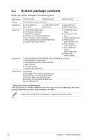
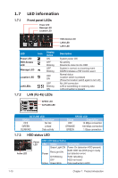
1.4 Front panel features The barebone server displays a simple yet stylish front panel with easily accessible features. The power and reset buttons, LED indicators, and USB port for each Node are located on the front panel. Refer to section 1.7.1 Front panel LEDs for the LED descriptions. Rack screw Hot-swap HDD bays Power LED Message LED Location LED LAN1 LED LAN2 LED HDD Access LED Hot-swap HDD bays Rack screw Hot-swap HDD bays Power button Reset button Location switch USB port Hot-swap HDD bays Turn off the system power and detach the power supply before removing or replacing any system component. 1-6 Chapter 1: Product introduction
-
 1
1 -
2
-
3
-
4
-
5
-
6
-
7
-
8
-
9
-
10
-
 11
11 -
 12
12 -
 13
13 -
 14
14 -
 15
15 -
 16
16 -
 17
17 -
 18
18 -
 19
19 -
 20
20 -
 21
21 -
22
-
23
-
24
-
25
-
26
-
27
-
28
-
29
-
30
-
31
-
32
-
33
-
34
-
35
-
36
-
37
-
38
-
39
-
40
-
41
-
42
-
43
-
44
-
45
-
46
-
47
-
48
-
49
-
50
-
51
-
52
-
53
-
54
-
55
-
56
-
57
-
58
-
59
-
60
-
61
-
62
-
63
-
64
-
65
-
66
-
67
-
68
-
69
-
70
-
71
-
72
-
73
-
74
-
75
-
76
-
77
-
78
-
79
-
80
-
81
-
82
-
83
-
84
-
85
-
86
-
87
-
88
-
89
-
90
-
91
-
92
-
93
-
94
-
95
-
96
-
97
-
98
-
99
-
100
-
101
-
102
-
103
-
104
-
105
-
106
-
107
-
108
-
109
-
110
-
111
-
112
-
113
-
114
-
115
-
116
-
117
-
118
-
119
-
120
-
121
-
122
-
123
-
124
-
125
-
126
-
127
-
128
-
129
-
130
-
131
-
132
-
133
-
134
-
135
-
136
-
137
-
138
-
139
-
140
-
141
-
142
-
143
-
144
-
145
-
146
-
147
-
148
-
149
-
150
-
151
-
152
-
153
-
154
-
155
-
156
-
157
-
158
-
159
-
160
-
161
-
162
-
163
-
164
 |
 |

Chapter 1:
Product introduction
1-6
1.4
Front panel features
The barebone server displays a simple yet stylish front panel with easily accessible
features. The power and reset buttons, LED indicators, and USB port for each
Node are located on the front panel.
Refer to section
1.7.1 Front panel LEDs
for the LED descriptions.
Hot-swap
HDD bays
Rack
screw
Rack
screw
USB port
LAN2 LED
HDD Access LED
LAN1 LED
Message LED
Power button
Location switch
Reset button
Location LED
Power LED
Hot-swap
HDD bays
Hot-swap
HDD bays
Hot-swap
HDD bays
Turn off the system power and detach the power supply before removing or
replacing any system component.