Asus Z8PH-D12 SE QDR -Manual
Asus Z8PH-D12 SE QDR Manual
 |
View all Asus Z8PH-D12 SE QDR manuals
Add to My Manuals
Save this manual to your list of manuals |
Asus Z8PH-D12 SE QDR manual content summary:
- Asus Z8PH-D12 SE QDR | -Manual - Page 1
Motherboard Z8NH-D12 Series Z8NH-D12 Z8PH-D12/IFB Z8PH-D12 SE/QDR - Asus Z8PH-D12 SE QDR | -Manual - Page 2
Product warranty or service will not be extended if: (1) the product is repaired, modified or altered, unless such repair, modification of alteration is authorized in writing by ASUS; or (2) the serial number of the product is defaced or missing. ASUS PROVIDES THIS MANUAL "AS IS" WITHOUT WARRANTY - Asus Z8PH-D12 SE QDR | -Manual - Page 3
guide ix Typography x Z8NH-D12 Series specifications summary xi Chapter 1: Product introduction 1.1 Welcome 1-3 1.2 Package contents 1-3 1.3 Serial number label 1-4 1.4 Special features 1-4 1.4.1 Product highlights 1-4 1.4.2 Innovative ASUS 21 2.5.5 Installing ASMB4 management board 2-21 iii - Asus Z8PH-D12 SE QDR | -Manual - Page 4
Using the dual function power switch 3-4 Chapter 4: BIOS setup 4.1 Managing and updating your BIOS 4-3 4.1.1 AFUDOS utility 4-3 4.1.2 ASUS CrashFree BIOS 4.3 Main menu 4-10 4.3.1 System Time [xx:xx:xx 4-10 4.3.2 System Date [Day xx/xx/xxxx 4-10 4.3.3 SATA1-4 4-10 4.3.4 IDE Configuration 4-12 - Asus Z8PH-D12 SE QDR | -Manual - Page 5
Power On Configuration 4-27 4.4.7 Event Log Configuration 4-28 4.4.8 Hardware Monitor 4-28 4.4.9 I/O Virtualization 4-30 4.4.10 PCI Express Configuration 4-30 4.4.11 ACPI Configuration 4-31 4.5 Server Adding or viewing a RAID configuration 5-12 5.2.3 Initializing the virtual drives 5-13 - Asus Z8PH-D12 SE QDR | -Manual - Page 6
OS 6-9 6.1.4 SUSE Linux Enterprise Server OS 6-17 6.2 Intel chipset support DVD 6-37 6.6.2 Drivers menu 6-37 6.6.3 Utilities menu 6-38 6.6.4 Make disk menu 6-38 6.6.5 Contact information 6-38 Reference information A.1 Z8NH-D12 block diagram A-3 A.2 Z8PH-D12/IFB block diagram A-4 A.3 Z8PH-D12 - Asus Z8PH-D12 SE QDR | -Manual - Page 7
energy and, if not installed and used in accordance with manufacturer' s instructions, may cause harmful interference to radio communications. However, there is no guarantee , we published the chemical substances in our products at ASUS REACH website at http://green.asus.com/english/REACH.htm. vii - Asus Z8PH-D12 SE QDR | -Manual - Page 8
are using, contact your local power company. • If the power supply is broken, do not try to fix it by yourself. Contact a qualified service technician or your retailer. Operation safety • Before installing the motherboard and adding devices on it, carefully read all the manuals that came with the - Asus Z8PH-D12 SE QDR | -Manual - Page 9
when installing and configuring the motherboard. How this guide is organized This user guide contains the following parts: • Chapter 1: Product introduction This chapter describes the features of the motherboard and the new technologies it supports. • Chapter 2: Hardware information This chapter - Asus Z8PH-D12 SE QDR | -Manual - Page 10
manual. DANGER/WARNING: Information to prevent injury to yourself when trying to complete a task. CAUTION: Information to prevent damage to the components when trying to complete a task. IMPORTANT: Instructions exactly as shown, then supply the required item or value enclosed in brackets. Example - Asus Z8PH-D12 SE QDR | -Manual - Page 11
specifications summary Model Name Processor Support / System Bus Core Logic Z8NH-D12 Z8PH-D12/IFB Z8PH-D12 SE/QDR 2 * socket 1366 Six/ 16.7" ASUS Features Fan Speed V V V Control Rack Ready V V V (Rack and Pedestal dual use) ASWM V V V Memory Total Slots 12 (3-channel per - Asus Z8PH-D12 SE QDR | -Manual - Page 12
are not compatible with SSI power supply. USE THE PROPRIETARY POWER SUPPLY ONLY; otherwise you may damage the motherboard. • The 4-pin Molex connector is designed for hard disk drive only. DO NOT connect other 4-pin power connectors of the power supply unit (PSU) to this connector. DO NOT - Asus Z8PH-D12 SE QDR | -Manual - Page 13
This chapter describes the motherboard introPdruoc1dtuiocnt features and the new technologies it supports. - Asus Z8PH-D12 SE QDR | -Manual - Page 14
Chapter summary 1 1.1 Welcome 1-3 1.2 Package contents 1-3 1.3 Serial number label 1-4 1.4 Special features 1-4 ASUS Z8NH-D12 Series - Asus Z8PH-D12 SE QDR | -Manual - Page 15
. 1.2 Package contents Check your motherboard package for the following items. Application CD Support CD Documentation User Guide Packing Qty. Standard Bulk Pack Z8NH-D12 Series 1 1 10pcs per carton If any of the above items is damaged or missing, contact your retailer. ASUS Z8NH-D12 Series 1-3 - Asus Z8PH-D12 SE QDR | -Manual - Page 16
number of the product, ASUS Technical Support team members can then offer a quicker and satisfying solution to your problems. Z8NH-D12 xxS2xxxxxxxxx Made in China 合格 1.4 Special features 1.4.1 Product highlights Latest processor technology This motherboard supports the latest Intel Xeon 5500 - Asus Z8PH-D12 SE QDR | -Manual - Page 17
requirements. USB 2.0 technology The motherboard implements the Universal Serial Bus (USB) 2.0 specification, dramatically increasing the connection speed from the 12 Mbps bandwidth on USB 1.1 to a fast 480 Mbps on USB 2.0. USB 2.0 is backward compatible with USB 1.1. ASUS Z8NH-D12 Series 1-5 - Asus Z8PH-D12 SE QDR | -Manual - Page 18
Capacitors This motherboard uses all high-quality conductive polymer capacitors for durability, improved lifespan, and enhanced thermal capacity. 1.4.2 Innovative ASUS features ASUS EPU With current trends leaning towards power efficiency, the Z8NH-D12 Series is equipped with the ASUS exclusive EPU - Asus Z8PH-D12 SE QDR | -Manual - Page 19
This chapter lists the hardware setup procedures that you have to perform when installing system components. It includes description of the jumpers and connectors on the motherboard. 2 Hardware information - Asus Z8PH-D12 SE QDR | -Manual - Page 20
Chapter summary 2 2.1 Before you proceed 2-3 2.2 Motherboard overview 2-5 2.3 Central Processing Unit (CPU 2-11 2.4 System memory 2-16 2.5 Expansion slots 2-19 2.6 Jumpers 2-22 2.7 Connectors 2-28 ASUS Z8NH-D12 Series - Asus Z8PH-D12 SE QDR | -Manual - Page 21
the system is ON, in sleep mode, or in soft-off mode. This is a reminder that you should shut down the system and unplug the power cable before removing or plugging in any motherboard component. The illustration below shows the location of the onboard LED. ASUS Z8NH-D12 Series 2-3 - Asus Z8PH-D12 SE QDR | -Manual - Page 22
2. CPU warning LED (ERR_CPU1, ERR_CPU2) The CPU warning LEDs light up to indicate that an impending failure of the corresponding CPU. 2-4 Chapter 2: Hardware information - Asus Z8PH-D12 SE QDR | -Manual - Page 23
chassis as indicated in the image below. 2.2.2 Screw holes Place eight (8) screws into the holes indicated by circles to secure the motherboard to the chassis. DO NOT overtighten the screws! Doing so can damage the motherboard. Place this side towards the rear of the chassis ASUS Z8NH-D12 Series - Asus Z8PH-D12 SE QDR | -Manual - Page 24
2.2.4 Motherboard layouts Z8NH-D12 2-6 Chapter 2: Hardware information - Asus Z8PH-D12 SE QDR | -Manual - Page 25
Z8PH-D12/IFB ASUS Z8NH-D12 Series 2-7 - Asus Z8PH-D12 SE QDR | -Manual - Page 26
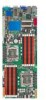
Z8PH-D12 SE/QDR 2-8 Chapter 2: Hardware information - Asus Z8PH-D12 SE QDR | -Manual - Page 27
Page 2-21 2-22 2-22 2-23 2-23 2-24 Rear panel connectors 1. RJ-45 port for iKVM 2. USB 2.0 ports 1 and 2 3. LAN 1 (RJ-45) port 4. LAN 2 (RJ-45) port 5. Serial (COM1) port 6. Video Graphics Adapter port 7. Location LED Page 2-25 2-25 2-25 2-25 2-25 2-25 2-25 ASUS Z8NH-D12 Series 2-9 - Asus Z8PH-D12 SE QDR | -Manual - Page 28
card connector (14-1 pin LPC1) 6. Serial General Purpose Input/Output connector (6-1 pin SGPIO1) 7. BMC header (BMC_FW1) 8. Power Supply SMBus connectors (6-1 pin JP1; JP2) 9. Proprietary power connectors (20-pin PWR1, 20-pin PWR2, 4-pin PWR3) 10. System panel connector (20-1 pin PANEL1 - Asus Z8PH-D12 SE QDR | -Manual - Page 29
/removal, or misplacement/loss/ incorrect removal of the PnP cap. 2.3.1 Installing the CPU To install a CPU: 1. Locate the CPU socket on the motherboard. Before installing the CPU, ensure that the socket box is facing toward you and the load lever is on your left. ASUS Z8NH-D12 Series 2-11 - Asus Z8PH-D12 SE QDR | -Manual - Page 30
º angle. 4. Lift the load plate with your thumb and forefinger to a 100º angle. Load plate 4 3 5. Remove the PnP cap from the CPU socket. PnP cap 2-12 Chapter 2: Hardware information - Asus Z8PH-D12 SE QDR | -Manual - Page 31
off immediately and seek professional medical help. To prevent contaminating the Thermal Interface Material, DO NOT spread the Thermal Interface Material with your finger directly. ASUS Z8NH-D12 Series 2-13 - Asus Z8PH-D12 SE QDR | -Manual - Page 32
2.3.2 Installing the CPU heatsink and fan The Intel Xeon 5500 series processors require a specially designed heatsink to ensure optimum thermal condition and performance. • Ensure to use qualified heatsink assembly only. • Ensure that you have applied the thermal - Asus Z8PH-D12 SE QDR | -Manual - Page 33
the fan cable to any of the the 4‑pin connectors. 3. ���R��e�p�e��a�t�s�t�e�p��s�1��t�o��3��to��i�n�s�t�a�l�l �th��e��o�th��e�r�h��e�a�t�s�in��k�i�f�y�o��u��h�a�v�e��i�n�s�t�a�l�le�d��a��s�e��c�o�n�d� CPU, then connect the fan cable to another 4‑pin connector. ASUS Z8NH-D12 Series 2-15 - Asus Z8PH-D12 SE QDR | -Manual - Page 34
2.4 System memory 2.4.1 Overview The motherboard comes with twelve (12) Double Data Rate 3 (DDR3) Dual Inline Memory Modules (DIMM) sockets. A DDR3 module has the same physical dimensions as a DDR2 DIMM but is notched differently to prevent installation on a DDR2 DIMM - Asus Z8PH-D12 SE QDR | -Manual - Page 35
1 DIMMs -- 2 DIMMs -- 3 DIMMs -- 4 DIMMs 6 DIMMs CPU 2 Configuration DIMM_D2 1 DIMMs -- 2 DIMMs -- 3 DIMMs -- 4 DIMMs 6 DIMMs DIMM_A1 DIMM_D1 DIMM_B2 ----- DIMM_E2 ----- DIMM_B1 -- DIMM_E1 -- DIMM_C2 ----- DIMM_F2 ----- DIMM_C1 --- DIMM_F1 --- ASUS Z8NH-D12 Series 2-17 - Asus Z8PH-D12 SE QDR | -Manual - Page 36
the power supply before adding or removing DIMMs or other system components. Failure to do so can cause severe damage to both the motherboard and into a socket to avoid damaging the DIMM. • The DDR3 DIMM sockets do not support DDR and DDR2 DIMMs. DO NOT install DDR or DDR2 DIMMs to the DDR3 DIMM - Asus Z8PH-D12 SE QDR | -Manual - Page 37
system unit cover (if your motherboard is already installed in a chassis). 3. Remove the bracket opposite support "Share IRQ" or that the cards do not need IRQ assignments. Otherwise, conflicts will arise between the two PCI groups, making the system unstable and the card inoperable. ASUS Z8NH-D12 - Asus Z8PH-D12 SE QDR | -Manual - Page 38
Time Clock 9* 4 ACPI Mode when used 10* 5 IRQ Holder for PCI Steering 11* 6 IRQ Holder for PCI Steering 12* 7 PS/2 Compatible Mouse Port 13 8 Numeric Data Processor 14* 9 Primary IDE Channel 15* 10 Secondary IDE Channel * These IRQs are usually available for ISA or PCI devices - Asus Z8PH-D12 SE QDR | -Manual - Page 39
motherboard layout may vary with models. 2.5.5 Installing ASMB4 management board Follow the steps below to install an optional ASMB4 management board on your motherboard. 1. Locate the BMC_FW1 header on the motherboard. 2. Orient and press the ASMB4 management card in place. ASUS Z8NH-D12 Series - Asus Z8PH-D12 SE QDR | -Manual - Page 40
by erasing the CMOS RTC RAM data. The onboard button cell battery powers the RAM data in CMOS, which include system setup information such as system passwords. To erase the RTC RAM: 1. Turn OFF the computer and unplug the power cord. 2. Move the jumper cap from pins 1-2 (default) to pins 2-3. Keep - Asus Z8PH-D12 SE QDR | -Manual - Page 41
2. VGA controller setting (3-pin VGA_SW1) This jumper allows you to enable or disable the onboard VGA controller. Set to pins 1-2 to activate the VGA feature. ASUS Z8NH-D12 Series 2-23 - Asus Z8PH-D12 SE QDR | -Manual - Page 42
3. DDR3 voltage control setting (4-pin LVDDR3_SEL1; LVDDR3_SEL2) These jumpers allow you to adjust the DIMM voltage. Set to pins 1-2 to select 1.5V BIOS control, pins 2-3 to select 1.2V Force or 3-4 to select 1.35V Force. 2-24 Chapter 2: Hardware information - Asus Z8PH-D12 SE QDR | -Manual - Page 43
4. LAN controller setting (3-pin LAN_SW1, LAN_SW2) These jumpers allow you to enable or disable the onboard Intel® Intel 82574LGigabit LAN controllers. Set to pins 1-2 to activate the Gigabit LAN feature. ASUS Z8NH-D12 Series 2-25 - Asus Z8PH-D12 SE QDR | -Manual - Page 44
5. Intel® ICH10R SATA port S/W RAID setting (3-pin RAID_SEL1) This jumper allows you to select the Serial ATA RAID configuration utility to use when you create disk arrays. Place the jumper caps on pins 1-2 if you want to use the LSI Logic Embedded SATA RAID Setup Utility (default); otherwise, place - Asus Z8PH-D12 SE QDR | -Manual - Page 45
the original or latest BIOS for the motherboard (XXXXXX.ROM) and the AFUDOS.EXE utility. 2. Set the jumper to pins 2-3. 3. Insert the USB flash and turn on the system to update the BIOS. 4. Shut down the system. 5. Set the jumper back to pins 1-2. 6. Turn on the system. ASUS Z8NH-D12 Series 2-27 - Asus Z8PH-D12 SE QDR | -Manual - Page 46
2.7 Connectors 2.7.1 Rear panel connectors Z8NH-D12; Z8PH-D12/IFB Z8PH-D12 SE/QDR 9 1. RJ-45 port for iKVM. This RJ-45 port functions only when you install ASMB4 management card. 2. USB 2.0 ports 1 and 2. These two 4-pin Universal Serial Bus (USB) ports are available for connecting USB 2.0 devices - Asus Z8PH-D12 SE QDR | -Manual - Page 47
-D12 SE/QDR only) These indicators show the status of InfiniBand (MQSFP1). Infiniband (MQSFP1) indications Activity LED Link LED Off Off Orange Green Orange Blinking Green Description No device Device plugged in; Ready Device plugged in; Data transmitting ACT LED LINK LED ASUS Z8NH-D12 - Asus Z8PH-D12 SE QDR | -Manual - Page 48
2.7.2 Internal connectors 1. Serial ATA connectors (7-pin SATA1, SATA2, SATA3, SATA4) Supported by the Intel® ICH10R chipset, these connectors are for the Serial ATA signal cables for Serial ATA hard disk drives that allows up to 3Gb/s - Asus Z8PH-D12 SE QDR | -Manual - Page 49
that supports up to 480 Mbps connection speed. 3. Thermal sensor cable connectors (3-pin TR1, TR2) These connectors are for temperature monitoring. Connect the thermal sensor cables to these connectors and place the other ends to the devices, which you want to monitor temperature. ASUS Z8NH-D12 - Asus Z8PH-D12 SE QDR | -Manual - Page 50
support cooling fans of 350 mA-740 mA (8.88 W max.) or a total of 3.15 A-6.66 A (53.28 W max.) at +12V. Connect the fan cables to the fan connectors on the motherboard air flow inside the system may damage the motherboard components. • These are not jumpers! DO NOT place jumper caps on the fan - Asus Z8PH-D12 SE QDR | -Manual - Page 51
General Purpose Input/Output connector (6-1 pin SGPIO1) This connector is used for the SGPIO peripherals for the LSI MegaRAID and Intel Matrix RAID SATA LED. ASUS Z8NH-D12 Series 2-33 - Asus Z8PH-D12 SE QDR | -Manual - Page 52
) The BMC connector on the motherboard supports an ASUS® Server Management Board 4 Series (ASMB4). 8. Power Supply SMBus connectors (6-1 pin JP1; JP2) These connectors allow you to connect SMBus (System Management Bus) to the power supply unit to read PSU information. Devices communicate with an - Asus Z8PH-D12 SE QDR | -Manual - Page 53
more power-consuming devices. The system may become unstable or may not boot up if the power is inadequate. • USE THE PROPRIETARY POWER SUPPLY ONLY; otherwise you may damage the motherboard. Ensure that your PSU can provide at least the minimum power required by your system. ASUS Z8NH-D12 Series - Asus Z8PH-D12 SE QDR | -Manual - Page 54
10. System panel connector (20-pin PANEL1) This connector supports several chassis-mounted functions. 1. System power LED (3-pin PLED) This 3-pin connector is for the system power LED. Connect the chassis power LED cable to this connector. The system power LED lights up when you turn on the system - Asus Z8PH-D12 SE QDR | -Manual - Page 55
) This connector is for additional front panel features including front panel SMB, locator LED and switch, chassis intrusion, and LAN LEDs. 1. Front panel SMB (6-1 pin FPSMB) These leads connect the front front panel. This button queries the state of the system locator. ASUS Z8NH-D12 Series 2-37 - Asus Z8PH-D12 SE QDR | -Manual - Page 56
2-38 Chapter 2: Hardware information - Asus Z8PH-D12 SE QDR | -Manual - Page 57
This chapter describes the power up sequence, and ways of shutting down the system. 3 Powering up - Asus Z8PH-D12 SE QDR | -Manual - Page 58
Chapter summary 3 3.1 Starting up for the first time 3-3 3.2 Turning off the computer 3-4 ASUS Z8NH-D12 Series - Asus Z8PH-D12 SE QDR | -Manual - Page 59
seconds from the time you turned on the power, the system may have failed a power-on test. Check the jumper settings and connections or call your retailer for assistance. 7. At power on, hold down the key to enter the BIOS Setup. Follow the instructions in Chapter 4. ASUS Z8NH-D12 Series 3-3 - Asus Z8PH-D12 SE QDR | -Manual - Page 60
3.2 Powering off the computer 3.2.1 Using the OS shut down function If you are using Windows® 2000/2003 Server: 1. Click Start then key in comments. 7. Click OK. 3.2.2 Using the dual function power switch While the system is ON, pressing the power switch for less than four seconds puts the system to - Asus Z8PH-D12 SE QDR | -Manual - Page 61
This chapter tells how to change the system settings through the BIOS Setup menus. Detailed descriptions of the BIOS parameters are also provided. 4 BIOS setup - Asus Z8PH-D12 SE QDR | -Manual - Page 62
Chapter summary 4 4.1 Managing and updating your BIOS 4-3 4.2 BIOS setup program 4-7 4.3 Main menu 4-10 4.4 Advanced menu 4-16 4.5 Server menu 4-33 4.6 Boot menu 4-35 4.7 Exit menu 4-39 ASUS Z8NH-D12 Series - Asus Z8PH-D12 SE QDR | -Manual - Page 63
same as shown. 1. Copy the AFUDOS utility (afudos.exe) from the motherboard support CD to the bootable USB flash disk drive you created earlier. 2. Boot main filename and three alphanumeric characters for the extension name. A:\>afudos /oOLDBIOS1.rom Main filename Extension name ASUS Z8NH-D12 - Asus Z8PH-D12 SE QDR | -Manual - Page 64
2. Copy the AFUDOS utility (afudos.exe) from the motherboard support CD to the bootable�U��S��B��fl�a�s�h��d��is�k��d�r�i�v�e���y��o��u��c�r�e�a��te��d��e�a�r�li�e�r�. 3. 19(ASUS V2.07(03.11.24BB)) Copyright (C) 2002 American Megatrends, Inc. All rights reserved. WARNING!! Do not turn off power - Asus Z8PH-D12 SE QDR | -Manual - Page 65
Megatrends, Inc. All rights reserved. WARNING!! Do not turn off power during flash BIOS Reading file ....... done Reading flash ...... done Advance Check ...... Erasing flash ...... done Writing flash ...... done Verifying flash .... done Please restart your computer A:\> ASUS Z8NH-D12 Series 4-5 - Asus Z8PH-D12 SE QDR | -Manual - Page 66
that contains the updated BIOS file. Prepare a USB flash drive containing the updated motherboard BIOS before using this utility. Recovering the BIOS from a USB flash drive To version for this motherboard. Visit the ASUS website at www.asus.com to download the latest BIOS file. 4-6 Chapter 4: - Asus Z8PH-D12 SE QDR | -Manual - Page 67
to run this program. Press during the Power-On Self-Test (POST) to enter the Setup or by pressing the reset button on the system chassis. You can also restart by turning the system ASUS website at www.asus.com to download the latest BIOS file for this motherboard. ASUS Z8NH-D12 Series 4-7 - Asus Z8PH-D12 SE QDR | -Manual - Page 68
, American Megatrends, Inc. Sub-menu items Navigation keys 4.2.2 Menu bar The menu bar on top of the screen has the following main items: Main Advanced Server Boot Exit For changing the basic system configuration For changing the advanced system settings For changing the advanced - Asus Z8PH-D12 SE QDR | -Manual - Page 69
menu bar displays the specific items for that menu. For example, selecting Main shows the Main menu items. The other items (Advanced, Power, Boot, and Exit) on the menu bar have their respective menu items of the menu screen is a brief description of the selected item. ASUS Z8NH-D12 Series 4-9 - Asus Z8PH-D12 SE QDR | -Manual - Page 70
on the menu screen items and how to navigate through them. Main Advanced BIOS SETUP UTILITY Server Boot Exit System Time [17:44:30] System Date [Mon, Ultra DMA :Ultra DMA-6 S.M.A.R.T.:Supported Disabled: Disabled LBA Mode. Auto: Enables LBA Mode if the device supports it and the device is - Asus Z8PH-D12 SE QDR | -Manual - Page 71
Enables or disables the LBA mode. Setting to [Auto] enables the LBA mode if the device supports this mode, and if the device was not previously formatted with LBA mode disabled. Configuration options 32-bit data transfer. Configuration options: [Disabled] [Enabled] ASUS Z8NH-D12 Series 4-11 - Asus Z8PH-D12 SE QDR | -Manual - Page 72
if you wish to configure the item. Main BIOS SETUP UTILITY IDE Configuration SATA Configuration Configure SATA as [IDE] Sets the configuration for the Serial ATA connectors supported by the Southbridge chip. Configuration options: [IDE] [RAID [25] [30] [35] 4-12 Chapter 4: BIOS setup - Asus Z8PH-D12 SE QDR | -Manual - Page 73
] [35] SATA Port1-4 [XXXX] Displays the status of auto-detection of SATA devices. Main BIOS SETUP UTILITY SATA Port1 Device :Not Detected SATA Port1 [Auto] SMART Monitoring [Enabled] Select and Reporting Technology. Configuration options: [Disabled] [Enabled] ASUS Z8NH-D12 Series 4-13 - Asus Z8PH-D12 SE QDR | -Manual - Page 74
you an overview of the general system specifications. The BIOS automatically detects the items in this menu. Main BIOS SETUP UTILITY AMIBIOS Version :0201 Build Date :02/25/10 Processor Speed Count :2266MHZ :1 System Memory Usable Size : 2040MB Onboard LAN1 Address : 00.E0.18.01.10.00 - Asus Z8PH-D12 SE QDR | -Manual - Page 75
CPU1/2 Memory Configuration Displays the auto-detected memory specification. Main CPU1 Memory Configuration Speed DDR3 1067 DIMM_A1 N/A DIMM_A2 N/A DIMM_B1 N/A DIMM_B2 N/A DIMM_C1 N/A DIMM_C2 N/A BIOS SETUP UTILITY ASUS Z8NH-D12 Series 4-15 - Asus Z8PH-D12 SE QDR | -Manual - Page 76
Main Advanced Server BIOS SETUP UTILITY Boot Exit CPU Configuration Chipset Configuration Legacy Device Configuration USB Configuration PCIPnP Configuration Power CPU does not support the related functions. L3 :12288 KB Ratio Status:Unlocked (Min:12, Max:17) Ratio Actual Value :17 Sets - Asus Z8PH-D12 SE QDR | -Manual - Page 77
HT Technology [Enabled] Active Processor Cores [All] A20M [ 12.0] [13.0] [14.0] [15.0] [16.0] [17.0]] C1E Support [Enabled] Allows you to enable or disable Enhanced Halt State support support for CPUs with extended CPUID functions. Configuration options: [Disabled] [Enabled] ASUS Z8NH-D12 - Asus Z8PH-D12 SE QDR | -Manual - Page 78
] Intel(R) TurboMode tech [Enabled] The turbo mode allows the processor cores to run faster than the marked frequency in specific condition allows the CPU to save more power under idle mode. Enable this item only when you install a C-State Technology-supported CPU. Configuration options: [Disabled] - Asus Z8PH-D12 SE QDR | -Manual - Page 79
that you set this item to [Auto] for BIOS to automatically detect the C-State mode supported by your CPU. Configuration options: [Auto] [C1] [C3] [C6] C3 Auto [Disabled] Enables or disables processor throttling report in ACPI. Configuration options: [Disabled] [Enabled] ASUS Z8NH-D12 Series 4-19 - Asus Z8PH-D12 SE QDR | -Manual - Page 80
4.4.2 Chipset Configuration The Chipset configuration menu allows you to change advanced chipset settings. Select an item then press to display the sub-menu. Advanced Advanced Chipset Settings BIOS SETUP UTILITY WARNING: Setting wrong values in below sections may cause system to - Asus Z8PH-D12 SE QDR | -Manual - Page 81
Disabled] [Enabled] CSI L1 [Disabled] Configuration options: [Disabled] [Enabled] CSI Power Optimization Policy [Static] Configuration options: [Adaptive] [Static] [Bypass] Memory Frequency or disables the ECC patrol scrub. Configuration options: [Disabled] [Enabled] ASUS Z8NH-D12 Series 4-21 - Asus Z8PH-D12 SE QDR | -Manual - Page 82
NUMA Aware [Auto] Configuration options: [Disabled] [Enabled] Page Poilcy [Open] Configuration options: [Closed] [Open] Adaptive Page [Disabled] Configuration options: [Disabled] [Enabled] Data Scramble [Enabled] Configuration options: [Disabled] [Enabled] Split Below 4 GB [Disabled] Configuation - Asus Z8PH-D12 SE QDR | -Manual - Page 83
item to [Disabled]. Configuration options: [6+6 USB Ports] [8+4 USB Ports] USB 2.0 Controller [Enabled] Allows you to enable or disable the USB 2.0 controller. Configuration options: [Enabled] [Disabled] ASUS Z8NH-D12 Series 4-23 - Asus Z8PH-D12 SE QDR | -Manual - Page 84
SLP_S4# Min. Assertion Width [1 to 2 seconds] Configuration options: [4 to 5 seconds] [3 to 4 seconds] [2 to 3 seconds] [1 to 2 seconds] Intel VT-d Configuration Advanced BIOS SETUP UTILITY Inel VT-d [Disabled] Options Disabled Enabled +F1 F10 ESC Select Screen Select Item Change Option - Asus Z8PH-D12 SE QDR | -Manual - Page 85
USB 2.0 controller to HiSpeed (480Mbps) or FullSpeed (12Mbps). Configuration options: [FullSpeed] [HiSpeed] BIOS EHCI Hand-Off [Enabled] Enables or disables the BIOS EHCI hand-off support. Configuration options: [Disabled] [Enabled] ASUS Z8NH-D12 Series 4-25 - Asus Z8PH-D12 SE QDR | -Manual - Page 86
4.4.5 PCIPnP Configuration The PCIPnP Configuration menu items allow you to change the advanced settings for PCI/PnP devices. Take caution when changing the settings of the PCI/PnP Configuration menu items. Incorrect field values can cause the system to malfunction. Advanced BIOS SETUP UTILITY - Asus Z8PH-D12 SE QDR | -Manual - Page 87
state, whatever the system state was before the AC power loss. Configuration options: [Power Off] [Power On] [Last State] Resume On Ring [Disabled] [12:30:30] Use the , or key to select a field. Use the or key to configure alarm time. ASUS Z8NH-D12 Series 4-27 - Asus Z8PH-D12 SE QDR | -Manual - Page 88
4.4.7 Event Log Configuration Main Advanced Event Logging details BIOS ] [ N/A ] [ N/A ] [High Density Mode] [ 1.052 V] [ N/A ] [ 1.508 V] [ N/A ] [ 1.520 V] [ 1.022 V] [ 1.022 V] [ 0.204 V] [12.000 V] CPU1 Temperature +F1 F10 ESC Select Screen Select Item Change Option General Help Save - Asus Z8PH-D12 SE QDR | -Manual - Page 89
(RPM). If the fan is not connected to the motherboard, the field shows [N/A]. Fan Speed Control [High Density Mode] Allows you to configure the ASUS Smart Fan feature that smartly adjusts the fan speeds for . Select [Ignored] if you do not want to detect this item. ASUS Z8NH-D12 Series 4-29 - Asus Z8PH-D12 SE QDR | -Manual - Page 90
.61 (C)Copyright 1985-2009, American Megatrends, Inc. SR-IOV Supported [Disabled] Configuration options: [Disabled] [Enabled] 4.4.10 PCI Configuration BIOS SETUP UTILITY Active State Power-Management [Disabled] Enable/Disable PCI Express L0s and L1 link power states. ←→ Select Screen ↑↓ Select - Asus Z8PH-D12 SE QDR | -Manual - Page 91
ACPI 2.0 Support [Enabled] Specifies the Advanced Configuration and Power Interface (ACPI) version supported. Configuration options: [Disabled] [Enabled] ACPI APIC Support [Enabled] the Headless operation mode through ACPI. Configuration options: [Disabled] [Enabled] ASUS Z8NH-D12 Series 4-31 - Asus Z8PH-D12 SE QDR | -Manual - Page 92
] [FED02000h] [FED03000h] General WHEA Configuration Advanced BIOS SETUP UTILITY General WHEA Configuration WHEA Support [Enabled] Enable or disable Windows Hardware Error Architecture. WHEA Support [Enabled] Allows you to enable or disable the Windows Hardware Error Architecture (WHEA - Asus Z8PH-D12 SE QDR | -Manual - Page 93
4.5 Server menu Main Advanced Server BIOS SETUP UTILITY Boot Exit Remote Access Configuration Configure Remote Access. +F1 F10 ESC Select . Configuration options: [Disabled] [Enabled] The following items appear only when Remote Access is set to [Enabled]. ASUS Z8NH-D12 Series 4-33 - Asus Z8PH-D12 SE QDR | -Manual - Page 94
for console redirection. Configuration options: [None] [Hardware] [Software] Redirection After BIOS POST [Disabled] Sets the redirection mode after the BIOS Power-On Self-Test (POST). Some operating system may not work when set to [Always]. Configuration options: [Disabled] [Boot Loader] [Always - Asus Z8PH-D12 SE QDR | -Manual - Page 95
boot options. Select an item then press to display the sub-menu. Main Advanced Server BIOS SETUP UTILITY Boot Exit Boot Settings Boot Device Priority Boot Settings Configuration Security Specifies sequence of the hard disk drives or the optical drives. ASUS Z8NH-D12 Series 4-35 - Asus Z8PH-D12 SE QDR | -Manual - Page 96
For 'F1' If Error Hit 'DEL' Message Display Interrupt 19 Capture [Enabled] [Enabled] Enabled] Enabling this item allows the BIOS to skip some power on self tests (POST) while booting to decrease the Set this item to [Enabled] to use the ASUS MyLogo2™ feature. AddOn ROM Display Mode [Force BIOS - Asus Z8PH-D12 SE QDR | -Manual - Page 97
, select the Change Supervisor Password then press . The message Password Uninstalled appears. If you forget your BIOS password, you can clear it by erasing the CMOS Real Time Clock (RTC) RAM. See section 2.6 Jumper for information on how to erase the RTC RAM. ASUS Z8NH-D12 Series 4-37 - Asus Z8PH-D12 SE QDR | -Manual - Page 98
you to change other security settings. Main Advanced BIOS SETUP UTILITY Server Power Boot Tools Supervisor Password : Installed User numbers, then press . 3. Confirm the password when prompted. The message Password Installed appears after you set your password successfully. To change the - Asus Z8PH-D12 SE QDR | -Manual - Page 99
save or discard your changes to the BIOS items. Main Advanced Server BIOS SETUP UTILITY Boot Exit Exit Options Exit & Save Setup program without saving your changes, the program prompts you with a message asking if you want to save your changes before exiting. Press < ASUS Z8NH-D12 Series 4-39 - Asus Z8PH-D12 SE QDR | -Manual - Page 100
4-40 Chapter 4: BIOS setup - Asus Z8PH-D12 SE QDR | -Manual - Page 101
This chapter provides instructions for setting up, creating, and configuring RAID sets using the available utilities. 5RAID configuration - Asus Z8PH-D12 SE QDR | -Manual - Page 102
Chapter summary 5 5.1 Setting up RAID 5-3 5.2 LSI Software RAID Configuration Utility 5-5 5.3 Intel® Matrix Storage Manager Option ROM Utility 5-25 ASUS Z8NH-D12 Series - Asus Z8PH-D12 SE QDR | -Manual - Page 103
this setup. If you want to boot the system from a hard disk drive included in a created RAID set, copy first the RAID driver from the support CD to a floppy disk before you install an operating system to the selected hard disk drive. ASUS Z8NH-D12 Series 5-3 - Asus Z8PH-D12 SE QDR | -Manual - Page 104
disks into the drive bays following the instructions in the system user guide. 2. Connect a SATA signal cable to the signal connector at the back of each drive and to the SATA connector on the motherboard. 3. Connect a SATA power cable to the power connector on each drive. 5.1.3 Setting the RAID - Asus Z8PH-D12 SE QDR | -Manual - Page 105
SATA hard disk drives connected to the SATA connectors supported by the motherboard southbridge chip. To enter the LSI MegaRAID software RAID has to be manually adjusted. Otherwise, the system will not boot from the connected SATA ODD. 3. The utility main window appears. ASUS Z8NH-D12 Series 5-5 - Asus Z8PH-D12 SE QDR | -Manual - Page 106
two types of configurations: Easy and New. In Easy Configuration, the virtual drive parameters are set automatically. In New Configuration, you manually set the virtual drive parameters. Using Easy Configuration To create a RAID set using the Easy Configuration option 1. From the Management Menu - Asus Z8PH-D12 SE QDR | -Manual - Page 107
MENU Select Configurable Array(s) PORT # A-0 SPAN-1 0 DNLIN A00-00 1 DNLIN A00-01 Cursor Keys, SPACE-(De)Select F2-ChIdInfo F3-SlotInfo F10-Configure Esc-Quit ASUS Z8NH-D12 Series 5-7 - Asus Z8PH-D12 SE QDR | -Manual - Page 108
5. Press again, the virtual drive information appears including a Virtual Drive menu that allows you to change the virtual drive parameters. LSI Software RAID Configuration Utility Ver A.60 Jul 30, 2008 BIOSVViretrusailonDrivAe.(0s8).C0o9n1f6ig1u3r4e4dR LD 0 RA1IEDasy - Asus Z8PH-D12 SE QDR | -Manual - Page 109
Accept SPAN = NO Accept This VD Configuration And Go To Next VD Cursor Keys, SPACE-(De)Select F2-ChIdInfo F3-SlotInfo F10-Configure Esc-Quit ASUS Z8NH-D12 Series 5-9 - Asus Z8PH-D12 SE QDR | -Manual - Page 110
11. Follow step 2 to 10 to configure additional virtual drives. 12. Press to finish RAID configuration. When prompted to save configuration, select Yes from the menu, and then press . LSI Software RAID Configuration Utility - Asus Z8PH-D12 SE QDR | -Manual - Page 111
= On Accept SPAN = NO Enter VD Size (MB): Use Cursor Keys to Navigate Between Items And Press Enter To Select An Option 5. Follow step 8 to 12 of the previous section: Using Easy Configuration to create the RAID set. ASUS Z8NH-D12 Series 5-11 - Asus Z8PH-D12 SE QDR | -Manual - Page 112
-Drive Info,F3-Virtual Drives,F4-HSP The information of the selected hard disk drive displays at the bottom of the screen. 3. Follow step 3 to 12 of section 5.2.1 Creating a RAID set: Using Easy Configuration to add a new RAID set - Asus Z8PH-D12 SE QDR | -Manual - Page 113
Size #Stripes StripSz Status Configure Initialize 0 1 151634MB 2 64 KB ONLINE Objects Rebuild Check Consistency Virtual Drives Virtual Drive 0 Select VD SPACE-(De)Select, F10-Initialize ASUS Z8NH-D12 Series 5-13 - Asus Z8PH-D12 SE QDR | -Manual - Page 114
3. Press to start initialization. When prompted, select Yes from the Initialize? dialog box, and then press . LSI Software RAID Configuration Utility Ver A.60 Jul 30, 2008 BIOS Version A.08.09161344R Virtual Drive(s) Configured Management Menu LD RAID Size #Stripes StripSz Status - Asus Z8PH-D12 SE QDR | -Manual - Page 115
Drive 0 Objects Management MAednaupter Configure Virtual Drive Initialize Physical Drive Objects Rebuild Check Consistency Select VD Press ENTER To Select A VD, To Delete A VD ASUS Z8NH-D12 Series 5-15 - Asus Z8PH-D12 SE QDR | -Manual - Page 116
3. Select Initialize from the pop-up menu, and then press to start initialization. LSI Software RAID Configuration Utility Ver A.60 Jul 30, 2008 BIOS Version A.08.09161344R Vitual Drive(1) Virtual Drive 0 Objects Management MAednaupter Configure Virtual Drive Initialize Physical Drive - Asus Z8PH-D12 SE QDR | -Manual - Page 117
5.2.4 Rebuilding failed drives You can manually rebuild failed hard disk drives using the Rebuild command in the Management Menu. To rebuild a failed # 1 DISK 77247MB HDS728080PLA380 PF20A60A SPACE-(De)Select,F10-Start Rebuild,F2-Drive Information,F3-View Virtual Drives ASUS Z8NH-D12 Series 5-17 - Asus Z8PH-D12 SE QDR | -Manual - Page 118
3. After selecting the drive to rebuild, press . When prompted, press to rebuild the drive. LSI Software RAID Configuration Utility Ver A.60 Jul 30, 2008 BIOS Version A.08.09161344R REBUILD - PHYSICAL DRIVES SELECTION MENU Management Menu Configure PORT # Initialize 0 ONLIN A00-00 - Asus Z8PH-D12 SE QDR | -Manual - Page 119
StripSz Status Configure 0 10 154494MB 4 64 KB ONLINE Initialize Objects Rebuild Check Consistency Virtual Drives Virtual Drive 0 Select VD SPACE-(De)Select, F10-Check Consistency ASUS Z8NH-D12 Series 5-19 - Asus Z8PH-D12 SE QDR | -Manual - Page 120
3. When prompted, use the arrow keys to select Yes from the Consistency Check? dialog box, and then press . LSI Software RAID Configuration Utility Ver A.60 Jul 30, 2008 BIOS Version A.08.09161344R Virtual Drive(s) Configured Management Menu LD RAID Size #Stripes StripSz Status Configure - Asus Z8PH-D12 SE QDR | -Manual - Page 121
prompted, use the arrow keys to select Yes from the dialog box to check the drive. 5. When checking is complete, press any key to continue. ASUS Z8NH-D12 Series 5-21 - Asus Z8PH-D12 SE QDR | -Manual - Page 122
5.2.6 Deleting a RAID configuration To delete a RAID configuration 1. From the Management Menu, select Configure > Clear Configuration, and then press . LSI Software RAID Configuration Utility Ver A.60 Jul 30, 2008 BIOS Version A.08.09161344R Configuration Menu Easy Configuration - Asus Z8PH-D12 SE QDR | -Manual - Page 123
Keys To Navigate Between Items And Press Enter To Select An Option 3. The virtual drive is selected as boot drive. Press any key to continue. ASUS Z8NH-D12 Series 5-23 - Asus Z8PH-D12 SE QDR | -Manual - Page 124
5.2.8 Enabling WriteCache You may manually enable the RAID controller's WriteCache option after creating a RAID set to improve the data transmission performance. When you enable WriteCache, you may lose data when a power interruption occurs while transmitting or exchanging data among the drives. The - Asus Z8PH-D12 SE QDR | -Manual - Page 125
2. Turn on the system. 3. During POST, press to display the utility main menu. Intel(R) Matrix Storage Manager option ROM v8.5.0.1030 ICH10R/DO wRAID5 Copyright(C) 2003- on your screen. The utility supports maximum four hard disk drives for RAID configuration. ASUS Z8NH-D12 Series 5-25 - Asus Z8PH-D12 SE QDR | -Manual - Page 126
5.3.1 Creating a RAID set To create a RAID set 1. From the utility main menu, select 1. Create RAID Volume and press . The following screen appears. Intel(R) Matrix Storage Manager option ROM v8.5.0.1030 ICH10R/DO wRAID5 Copyright(C) 2003- - Asus Z8PH-D12 SE QDR | -Manual - Page 127
for server systems, and a higher stripe size for multimedia computer systems used mainly for message appears. WARNING: ALL DATA ON SELECTED DISKS WILL BE LOST. Are you sure you want to create this volume? (Y/N): 9. Press to create the RAID volume and return to the main ASUS Z8NH-D12 Series 5-27 - Asus Z8PH-D12 SE QDR | -Manual - Page 128
7. When the Create Volume item is selected, press . The following warning message appears. WARNING: ALL DATA ON SELECTED DISKS WILL BE LOST. Are you sure volume? (Y/N): 8. Press to create the recovery set and return to the main menu, or to go back to the CREATE VOLUME menu. If a - Asus Z8PH-D12 SE QDR | -Manual - Page 129
select the RAID set you want to delete, and then press . The following warning message appears. [ DELETE VOLUME VERIFICATION ] ALL DATA IN THE VOLUME WILL BE LOST! (This RAID set and return to the utility main menu, or press to return to the DELETE VOLUME menu. ASUS Z8NH-D12 Series 5-29 - Asus Z8PH-D12 SE QDR | -Manual - Page 130
ST3160812AS Serial # 9LS0HJA4 9LS0F4HL Size Status 149.0GB Member Disk 149.0GB Member Disk Select the disks that should be reset. drive(s). A confirmation message appears. 4. Press to reset the drive(s) or press to return to the utility main menu. 5-30 Chapter 5: RAID - Asus Z8PH-D12 SE QDR | -Manual - Page 131
create a recovery set before continue. To configure a recovery set 1. From the utility main menu, select 4. Recovery Volume Options and press . The following screen appears. Intel . Press after completing your selection and return to the utility main menu. ASUS Z8NH-D12 Series 5-31 - Asus Z8PH-D12 SE QDR | -Manual - Page 132
menu, select 5. Exit, and then press . The following warning message appears. [ CONFIRM EXIT ] Are you sure you want to exit? (Y/N): 2. Press to exit or press to return to the utility main menu. 5.3.7 Rebuilding the RAID This option is only for the RAID 1 set. Rebuilding the RAID - Asus Z8PH-D12 SE QDR | -Manual - Page 133
DO wRAID5 Copyright(C) 2003-08 Intel Corporation. All Rights Reserved. [ MAIN MENU ] 1. Create RAID Volume 2. Delete RAID Volume 5. Exit 3LS0JYL8 Size Type/Status(Vol ID) 149.0GB Member Disk(0) 149.0GB Member Disk(0) Volumes with "Rebuild" status will be 32. ASUS Z8NH-D12 Series 5-33 - Asus Z8PH-D12 SE QDR | -Manual - Page 134
5.3.8 Setting the Boot array in the BIOS Setup Utility You can set the boot priority sequence in the BIOS for your RAID arrays when creating multi-RAID using the Intel® Matrix Storage Manager. To set the boot array in the BIOS: Set at least one of the arrays bootable to boot from the hard disk. 1. - Asus Z8PH-D12 SE QDR | -Manual - Page 135
This chapter provides instructions for installing the necessary drivers for different system components. 6Driver installation - Asus Z8PH-D12 SE QDR | -Manual - Page 136
installation 6-23 6.4 Display driver installation 6-27 6.5 Mellanox ConnectX DDR and ConnectX2 QDR PCI Gen2 Channel Adapter driver installation 6-30 6.6 Management application and utilities installation 6-37 ASUS Z8NH-D12 Series - Asus Z8PH-D12 SE QDR | -Manual - Page 137
instructions on how to install the RAID controller drivers during OS installation. 6.1.1 Creating a RAID driver disk You may have to use another system to create the RAID driver disk from the system/motherboard support want to ceate and press to enter the sub-menu. ASUS Z8NH-D12 Series 6-3 - Asus Z8PH-D12 SE QDR | -Manual - Page 138
RAID Driver ICH10R LSI RAID Driver Windows XP 32 bit Windows XP 64 bit Windows Server 2003 32 bit Windows Server 2008 64 bit Windows Vista 32 bit Windows Vista 64 bit Windows Server 2008 32 bit Windows Server 2008 64 bit RHEL AS4 UP6 32/64 bit RHEL AS4 UP7 32/64 bit - Asus Z8PH-D12 SE QDR | -Manual - Page 139
7 32/64 bit Back Exit 6. Locate the RAID driver and place a blank, high-density floppy disk to the floppy disk drive. 7. Press . 8. Follow screen instructions to create the driver disk. ASUS Z8NH-D12 Series 6-5 - Asus Z8PH-D12 SE QDR | -Manual - Page 140
® OS installation CD. The Window® Setup starts. 2. Press when the message "Press F6 if you need to install a third party SCSI or RAID driver..." in your system, or you have chosen to manually specify an adapter. Currently, Setup will load support for the following mass storage devices(s): - Asus Z8PH-D12 SE QDR | -Manual - Page 141
drive, then press . Windows Setup Please insert the disk labeled Manufacturer-supplied hardware support disk into Drive A: * Press ENTER when ready. ENTER=Continue ESC=Cancel F3 Setup then proceeds with the OS installation. Follow screen instructions to continue. ASUS Z8NH-D12 Series 6-7 - Asus Z8PH-D12 SE QDR | -Manual - Page 142
To an existing Windows® OS To install the RAID controller driver on an existing Windows® OS: 1. Restart the computer, then log in with Administrator privileges. 2. Windows® automatically detects the RAID controller and displays a New Hardware Found window. Click Cancel. 3. Right-click the My - Asus Z8PH-D12 SE QDR | -Manual - Page 143
Use the function keys listed below for more information. [F1-Main] [F2-Options] [F3-General] [F4-Kernel] [F5- Main Menu Do you have a driver disk? Yes No 5. Press to continue. Insert Driver Disk Insert your driver disk into /dev/sda and press "OK" to continue. OK Cancel ASUS Z8NH-D12 - Asus Z8PH-D12 SE QDR | -Manual - Page 144
6. Select No and press to continue. More Driver Disks? Do you wish to load any more driver disks? Yes No 7. Select your desired language and press to continue. Choose a Language What language would you like to use during the installation process? Catalan Chinese(Simplified) # - Asus Z8PH-D12 SE QDR | -Manual - Page 145
OK. Press to continue. No driver found Unable to find any devices of the type needed for this installation type. Would you like to manually select your driver or use a driver disk? Select driver Use a driver disk Back ASUS Z8NH-D12 Series 6-11 - Asus Z8PH-D12 SE QDR | -Manual - Page 146
module arguments OK Back The driver version may vary with time and model. Select LSI Mega Software RAID driver (LSI megasr Driver) all the time. 12. Select Skip and press to continue. CD Found To begin testing the CD media before installation press OK. Choose Skip to skip the media - Asus Z8PH-D12 SE QDR | -Manual - Page 147
(megasr) USB Mass Storage driver for Linux (usb-storage) Done Add Device The displayed devices may vary with models and systems. 14. Follow the onscreen instructions to finish installing the RedHat operating system. ASUS Z8NH-D12 Series 6-13 - Asus Z8PH-D12 SE QDR | -Manual - Page 148
, press the key. - To install or upgrade in text mode, type: linux text . - Use the function keys listed below for more information. [F1-Main] [F2-Options] [F3-General] [F4-Kernel] [F5-Rescue] boot: linux dd noprobe=ata[n] 4. Select Yes using the key when asked if you have the - Asus Z8PH-D12 SE QDR | -Manual - Page 149
More Driver Disks? Do you wish to load any more driver disks? Yes No 8. Follow the onscreen instructions to finish the OS installation. 9. If you install RHEL AS5, when the installation is completed, DO NOT dev/fd0 /mnt/driver cd /mnt/driver sh replace_ahci.sh reboot ASUS Z8NH-D12 Series 6-15 - Asus Z8PH-D12 SE QDR | -Manual - Page 150
Type the following commands when using a USB floppy. cat /proc/partitions Write down the Major and Minor number before sdb for later use. mknod /dev/sdb b [major number] [minor number] mkdir /mnt/driver mount /dev/sdb /mnt/driver cd /mnt/driver sh replace_ahci.sh reboot 6-16 Chapter 6: Driver - Asus Z8PH-D12 SE QDR | -Manual - Page 151
6.1.4 SUSE Linux Enterprise Server OS To install the RAID controller driver when installing�S��U�S��E��L�i�n�u�x��E�n�t�e�r�p�r�is�e��S��e�r�v�e�r OS: 1. Boot the system from the SUSE OS Boot Options | Yes No File F1 Help F2 Language F3 1280 x 1024 F4 DVD F5 Driver ASUS Z8NH-D12 Series 6-17 - Asus Z8PH-D12 SE QDR | -Manual - Page 152
4. Insert the RAID driver disk to the floppy disk drive. Make sure that Installation from the Boot Options menu is selected, then press . Boot from Hard Disk Installation Installation--ACPI Disabled Installation--Local APIC Disabled Installation--Safe Settings Rescue System Memory Test Boot - Asus Z8PH-D12 SE QDR | -Manual - Page 153
, then log on with Administrator privileges. 2. Insert the motherboard/system support DVD to the optical drive. The support DVD automatically displays the Drivers menu if Autorun is enabled in your computer. 3. Click the item Intel Chipset Device Software from the menu. ASUS Z8NH-D12 Series 6-19 - Asus Z8PH-D12 SE QDR | -Manual - Page 154
4. The Intel(R) Chipset Device Software window appears. Click Next to start the installation. 5. Select Yes to accept the terms of the License Agreement and continue the process. 6-20 Chapter 6: Driver installation - Asus Z8PH-D12 SE QDR | -Manual - Page 155
6. Read the Readme File Information and click Next to activate the installation. 7. After completing the installation, click Next to continue. ASUS Z8NH-D12 Series 6-21 - Asus Z8PH-D12 SE QDR | -Manual - Page 156
8. Click Yes, I want to restart this computer now and click Finish to restart the computer. 6-22 Chapter 6: Driver installation - Asus Z8PH-D12 SE QDR | -Manual - Page 157
is enabled in your computer. If Autorun is NOT enabled in your computer, browse the contents of the support DVD to locate the file AUTORUN.EXE and double-click the AUTORUN.EXE and follow step 4 to run the installation. 3. Click Intel® PRO/1000 Gigabit Adapters Driver. ASUS Z8NH-D12 Series 6-23 - Asus Z8PH-D12 SE QDR | -Manual - Page 158
4. When the Intel® PRO Network Connections - InstallShield Wizard window appears, click Next to start the installation. 5. Click I accept the terms in the license agreement and then click Next to continue. 6-24 Chapter 6: Driver installation - Asus Z8PH-D12 SE QDR | -Manual - Page 159
6. Select the programs you want to install and click Next to continue. 7. Click Install to start the installation. ASUS Z8NH-D12 Series 6-25 - Asus Z8PH-D12 SE QDR | -Manual - Page 160
8. The programs you select are being installed. 9. Click Finish to finish the installation. 6-26 Chapter 6: Driver installation - Asus Z8PH-D12 SE QDR | -Manual - Page 161
the motherboard/system support DVD to the optical drive. The support DVD automatically displays the Drivers menu if Autorun is enabled in your computer. 4. Click ASPEED AST2050 Display Driver. 4. When the ASPEED InstallShield Wizard window appears, click Next to continue. ASUS Z8NH-D12 Series - Asus Z8PH-D12 SE QDR | -Manual - Page 162
5. Click Install to start the installation. 6. The system installs the driver automatically. 6-28 Chapter 6: Driver installation - Asus Z8PH-D12 SE QDR | -Manual - Page 163
7. When the installation completes, click Finish to exit the wizard. 8. Click Yes to restart the computer. ASUS Z8NH-D12 Series 6-29 - Asus Z8PH-D12 SE QDR | -Manual - Page 164
system You need to manually install the Mellanox driver on a Windows® operating system. To install the Mellanox driver 1. Restart the computer, then log on with Administrator privileges. 2. Insert the motherboard/system support DVD to the optical drive. The support DVD automatically displays the - Asus Z8PH-D12 SE QDR | -Manual - Page 165
5. Click I accept the terms in the license agreement and click Next to continue. 5. Click Change to select your desired destination folder and click Next to continue. ASUS Z8NH-D12 Series 6-31 - Asus Z8PH-D12 SE QDR | -Manual - Page 166
6. Select a setup type and click Next to continue. 7. The driver features you selected are being installed. 6-32 Chapter 6: Driver installation - Asus Z8PH-D12 SE QDR | -Manual - Page 167
8. Click your preferred options and click Finish to exit the wizard. ASUS Z8NH-D12 Series 6-33 - Asus Z8PH-D12 SE QDR | -Manual - Page 168
6.5.2 Red Hat® Enterprise Linux OS You need to manually mount the Mellanox driver on a Red Hat® Enterprise Linux OS. For users using SUSE Linux Enterprise Server OS, follow the general instructions in this section to mount the Mellanox driver on your system. To mount the Mellanox driver 1. Login to - Asus Z8PH-D12 SE QDR | -Manual - Page 169
4. Type the command line and install the driver. 5. All other Mellanox, OEM, OFED, or distribution IB packages will be removevd. Press to continue. 6. The system starts uninstalling the previous version of OFED. ASUS Z8NH-D12 Series 6-35 - Asus Z8PH-D12 SE QDR | -Manual - Page 170
7. When the installation finishes, reboot your system to complete the installation. If your system has the latest firmware, no firmware update will occur. To force firmware update, type --force-fw-update. 6-36 Chapter 6: Driver installation - Asus Z8PH-D12 SE QDR | -Manual - Page 171
motherboard features. The contents of the support DVD are subject to change at any time without notice. Visit the ASUS website at www.asus.com for updates. 6.6.1 Running the support DVD Place the support and driver options vary under different operating system versions. ASUS Z8NH-D12 Series 6-37 - Asus Z8PH-D12 SE QDR | -Manual - Page 172
Utilities menu displays the software applications and utilities that the motherboard supports. Click an item to install. 6.6.4 Make disk menu Contact tab to display the ASUS contact information. You can also find this information on the inside front cover of this user guide. 6-38 Chapter 6: Driver - Asus Z8PH-D12 SE QDR | -Manual - Page 173
This appendix includes additional information that you may refer to when A configuring the motherboard. Reference information - Asus Z8PH-D12 SE QDR | -Manual - Page 174
Appendix summary A A.1 Z8NH-D12 block diagram A-3 A.2 Z8PH-D12/IFB block diagram A-4 A.3 Z8PH-D12 SE/QDR block diagram A-5 ASUS Z8NH-D12 Series - Asus Z8PH-D12 SE QDR | -Manual - Page 175
A.1 Z8NH-D12 block diagram ASUS Z8NH-D12 Series A-3 - Asus Z8PH-D12 SE QDR | -Manual - Page 176
A.2 Z8PH-D12/IFB block diagram A-4 Appendix A: Reference information - Asus Z8PH-D12 SE QDR | -Manual - Page 177
A.3 Z8PH-D12 SE/QDR block diagram ASUS Z8NH-D12 Series A-5 - Asus Z8PH-D12 SE QDR | -Manual - Page 178
A-6 Appendix A: Reference information
-
 1
1 -
 2
2 -
 3
3 -
 4
4 -
 5
5 -
 6
6 -
 7
7 -
8
-
9
-
10
-
11
-
12
-
13
-
14
-
15
-
16
-
17
-
18
-
19
-
20
-
21
-
22
-
23
-
24
-
25
-
26
-
27
-
28
-
29
-
30
-
31
-
32
-
33
-
34
-
35
-
36
-
37
-
38
-
39
-
40
-
41
-
42
-
43
-
44
-
45
-
46
-
47
-
48
-
49
-
50
-
51
-
52
-
53
-
54
-
55
-
56
-
57
-
58
-
59
-
60
-
61
-
62
-
63
-
64
-
65
-
66
-
67
-
68
-
69
-
70
-
71
-
72
-
73
-
74
-
75
-
76
-
77
-
78
-
79
-
80
-
81
-
82
-
83
-
84
-
85
-
86
-
87
-
88
-
89
-
90
-
91
-
92
-
93
-
94
-
95
-
96
-
97
-
98
-
99
-
100
-
101
-
102
-
103
-
104
-
105
-
106
-
107
-
108
-
109
-
110
-
111
-
112
-
113
-
114
-
115
-
116
-
117
-
118
-
119
-
120
-
121
-
122
-
123
-
124
-
125
-
126
-
127
-
128
-
129
-
130
-
131
-
132
-
133
-
134
-
135
-
136
-
137
-
138
-
139
-
140
-
141
-
142
-
143
-
144
-
145
-
146
-
147
-
148
-
149
-
150
-
151
-
152
-
153
-
154
-
155
-
156
-
157
-
158
-
159
-
160
-
161
-
162
-
163
-
164
-
165
-
166
-
167
-
168
-
169
-
170
-
171
-
172
-
173
-
174
-
175
-
176
-
177
-
178
 |
 |

Motherboard
Z8NH-D12 Series
Z8NH-D12
Z8PH-D12/IFB
Z8PH-D12 SE/QDR