Asus a7n8xx Motherboard DIY Troubleshooting Guide - Page 27
ASUS A7N8X-X Motherboard, Internal audio connectors 4-pin CD1, AUX1, MODEM1, Power Supply Thermal - a7n8x la motherboard
 |
View all Asus a7n8xx manuals
Add to My Manuals
Save this manual to your list of manuals |
Page 27 highlights
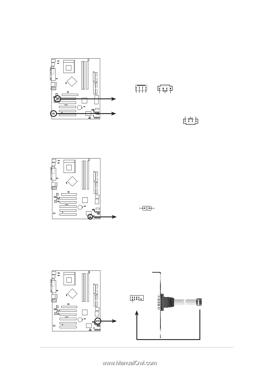
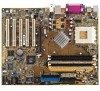
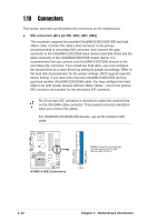
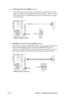
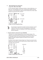
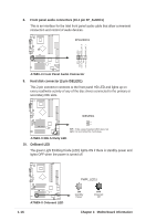
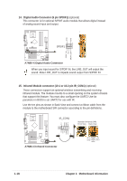
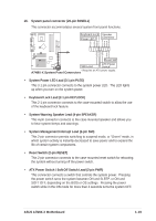
Modem-In Ground Ground Modem-Out Right Audio Channel Ground Left Audio Channel Left Audio Channel Ground Right Audio Channel 11. Internal audio connectors (4-pin CD1, AUX1, MODEM1) These connectors allow you to receive stereo audio input from sound sources such as a CD-ROM, TV tuner, MPEG card or modem. MODEM1 CD1 (Black) AUX1 (White) ® A7N8X-X A7N8X-X Internal Audio Connectors 12. Power Supply Thermal Sensor (2-pin PWRTMP1) This header supports a thermal sensor for the power supply. ® A7N8X-X PWRTMP1 PWRTMP Ground A7N8X-X Power Supply Thermal Connector 13. Serial Port 2 connector (10-1 pin COM2) (optional) This connector accomodates a second serial port using an optional serial port bracket. Connect the bracket cable to this connector then install the bracket into a slot opening at the back of the system chassis. ® A7N8X-X COM2 PIN 1 A7N8X-X Serial COM2 Bracket ASUS A7N8X-X Motherboard 1-17
-
 1
1 -
2
-
3
-
4
-
5
-
6
-
7
-
8
-
9
-
10
-
11
-
12
-
13
-
14
-
15
-
16
-
17
-
18
-
19
-
20
-
21
-
 22
22 -
 23
23 -
 24
24 -
 25
25 -
 26
26 -
 27
27 -
 28
28 -
 29
29 -
 30
30 -
 31
31 -
 32
32 -
33
-
34
-
35
-
36
-
37
-
38
-
39
-
40
-
41
-
42
-
43
-
44
-
45
-
46
-
47
-
48
-
49
-
50
-
51
-
52
-
53
-
54
-
55
-
56
-
57
-
58
-
59
-
60
 |
 |