Asus a7n8xx A7N8X-X User's Manual
Asus a7n8xx Manual
 |
View all Asus a7n8xx manuals
Add to My Manuals
Save this manual to your list of manuals |
Asus a7n8xx manual content summary:
- Asus a7n8xx | A7N8X-X User's Manual - Page 1
A7N8X-X User Guide Motherboard - Asus a7n8xx | A7N8X-X User's Manual - Page 2
express written permission of ASUSTeK COMPUTER INC. ("ASUS"). Product warranty or service will not be extended if: (1) the ASUS HAS BEEN ADVISED OF THE POSSIBILITY OF SUCH DAMAGES ARISING FROM ANY DEFECT OR ERROR IN THIS MANUAL OR PRODUCT. SPECIFICATIONS AND INFORMATION CONTAINED IN THIS MANUAL - Asus a7n8xx | A7N8X-X User's Manual - Page 3
information ...viii A7N8X-X specifications summary ...ix Features Chapter 1: Motherboard Info 1.1 1.2 1.3 1.4 1.5 1.6 1.7 Welcome! ...1-2 Package contents ...1-2 Motherboard components ...1-3 Motherboard layout ...1-6 Before you proceed ...1-7 Central Processing Unit (CPU) ...1-7 System memory - Asus a7n8xx | A7N8X-X User's Manual - Page 4
...2-22 Security Menu ...2-23 Hardware Monitor Menu ...2-24 Exit Menu ...2-26 Chapter 3: Starting Up 3.1 3.2 Install an operating system ...3-2 Support CD information ...3-2 3.2.1 Running the support CD ...3-2 3.2.2 Drivers menu ...3-3 3.2.3 Utilities menu ...3-3 3.2.4 ASUS Contact Information - Asus a7n8xx | A7N8X-X User's Manual - Page 5
used in accordance with manufacturer's instructions, may cause harmful interference to radio by turning the equipment off and on, the user is encouraged to try to correct the interference by radio/TV technician for help. The use of shielded cables for connection of the monitor to the graphics card - Asus a7n8xx | A7N8X-X User's Manual - Page 6
are using, contact your local power company. • If the power supply is broken, do not try to fix it by yourself. Contact a qualified service technician or your retailer. Operation safety • Before installing the motherboard and adding devices on it, carefully read all the manuals that came with the - Asus a7n8xx | A7N8X-X User's Manual - Page 7
this guide To make sure that you perform certain tasks properly, take note of the following symbols used throughout this manual. WARNING updates. 1. ASUS Websites The ASUS websites worldwide provide updated information on ASUS hardware and software products. The ASUS websites are listed in the ASUS - Asus a7n8xx | A7N8X-X User's Manual - Page 8
Drive, Fremont, CA 94538, USA +1-502-933-8713 [email protected] usa.asus.com Technical Support Support Fax: General Support: Notebook Support: Support Email: +1-502-933-8713 +1-502-995-0883 +1-510-739-3777 x5110 [email protected] ASUS COMPUTER GmbH (Germany and Austria) Address: General Email: General - Asus a7n8xx | A7N8X-X User's Manual - Page 9
LED connector, Power LED connector Chassis Intrusion, SIR Headphone (optional) Front MIC (optional) CD / AUX / Modem audio in Front Panel Audio connector (optional) (continued on the next page) Chipset Front Side Bus (FSB) Memory Expansion slots IDE Audio LAN Special Features Back Panel I/O Ports - Asus a7n8xx | A7N8X-X User's Manual - Page 10
DMI 2.0, WOL, WOR, Chassis Intrusion, SM Bus Device drivers ASUS PC Probe Trend Microtm PC-cillin 2002 anti-virus software ASUS LiveUpdate Utility User's manual Support CD 1 x UltraDMA 133/100/66 cable FDD cable 9-pin COM cable (optional) 2-port USB/Game port bracket (optional) I/O shield ATX - Asus a7n8xx | A7N8X-X User's Manual - Page 11
Chapter 1 ASUS A7N8X-X Motherboard Motherboard Info 1-1 This chapter gives information about the ASUS A7N8X-X motherboard that came with the system.This chapter includes the motherboard layout, jumper settings, and connector locations. - Asus a7n8xx | A7N8X-X User's Manual - Page 12
list below. 1.2 Package contents ASUS A7N8X-X motherboard ATX form factor: 12 in x 9.6 in ASUS A7N8X-X series support CD 40-pin 80-conductor ribbon cable for UltraDMA/66/100/133 IDE drives Ribbon cable for a 3.5-inch floppy drive Bag of extra jumper caps I/O shield User's Manual Check your ASUS - Asus a7n8xx | A7N8X-X User's Manual - Page 13
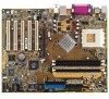
1.3 Motherboard components 1 2 3 4 5 6 18 17 7 16 15 8 9 10 11 14 13 12 19 20 21 22 23 24 28 27 26 25 ASUS A7N8X-X Motherboard 1-3 - Asus a7n8xx | A7N8X-X User's Manual - Page 14
1 2 CPU Sockets. Socket 462 (Socket A) Zero Insertion Force (ZIF) socket for the AMD Duron™/Athlon™/Athlon XP™ 3000+ processors. NorthBridge Controller. The NVIDIA® nForce2™ 400 North Bridge controller chipset. The controller supports a 64-bit DDR memory controller and up to 3 GB of 400/333/266/ - Asus a7n8xx | A7N8X-X User's Manual - Page 15
AC'97 compliant audio CODEC designed for PC multimedia systems. LAN chip. The MCP integrated NVIDIA® MAC + Realtek 8201BL PHY Fast Ethernet controller allows connection to a Local Area Network (LAN) through a network hub. AGP Slot. This Accelerated Graphics Port (AGP) slot only supports 1.5V AGP 8X - Asus a7n8xx | A7N8X-X User's Manual - Page 16
Audio Codec nForce2 MCP Chipset SPDIF1 PCI 2 ® Super I/O A7N8X-X CR2032 3V Lithium Cell CMOS Power CLRTC1 COM2 USB56 PCI 3 PCI 4 MODEM1 PWR_LED1 USBPWR_56 GAME1 PCI 5 with Hardware Monitor IDELED1 PWRTMP1 CHASSIS1 ASUS ASIC IR_CON1 CTRL_PANEL1 1-6 Chapter 1: Motherboard Information - Asus a7n8xx | A7N8X-X User's Manual - Page 17
-X supports Athlon™ XP processors with "QuantiSpeed" data processing, large data caches, 3D enhancements and 400/333/266Mhz bus speeds. Do not use processors with core speeds of less than 1GHz on this motherboard. CPU NOTCH TO INNER CORNER LOCK LEVER ® A7N8X-X AMD™ CPU CPU NOTCH A7N8X-X Socket - Asus a7n8xx | A7N8X-X User's Manual - Page 18
-X 80 Pins A7N8X-X 184-Pin DDR DIMM Sockets 1. DIMMs with more than 8 devices on each side of the module are not supported. 2. Make sure the memory frequency and bus frequency setting in the BIOS are the same or set to [Auto] ensure system stability. 3. A DDR DIMM is keyed with a notch so that - Asus a7n8xx | A7N8X-X User's Manual - Page 19
This motherboard has an Accelerated Graphics Port (AGP) slot that supports +1.5V AGP 8X cards. Note the notches on the card golden fingers to ensure that they fit the AGP slot on your motherboard. ® A7N8X-X Keyed for 1.5v A7N8X-X Accelerated Graphics Port (AGP) ASUS A7N8X-X Motherboard 1-9 - Asus a7n8xx | A7N8X-X User's Manual - Page 20
This section describes and illustrates the jumpers on the motherboard. USBPWR_56 ® A7N8X-X 1 2 +5V (Default) 2 3 +5VSB A7N8X-X USB Device Wake Up 2. Central Processing Unit FSB (CPU_FSB) This jumper when set to 1-2 pins (default), enable support for Front Side Bus 400/333/266. When set to pins - Asus a7n8xx | A7N8X-X User's Manual - Page 21
value is [Disabled]). This feature requires an ATX power supply that can supply at least 1A on the +5VSB lead, and a corresponding setting in the BIOS (see section 2.5.1 Power Up Control). KBPWR1 1 2 +5V (Default) ® 2 3 +5VSB A7N8X-X A7N8X-X Keyboard Power Setting ASUS A7N8X-X Motherboard 1-11 - Asus a7n8xx | A7N8X-X User's Manual - Page 22
. BIOS supports specific device bootup. If you have more than two UltraDMA/133/100/66 devices, purchase another UltraDMA/133/100/66 cable. You cables. For UltraDMA/133/100/66 IDE devices, use an 80-conductor IDE cable. SEC_IDE1 ® A7N8X-X PIN 1 A7N8X-X IDE Connectors 1-12 Chapter 1: Motherboard - Asus a7n8xx | A7N8X-X User's Manual - Page 23
supports the provided floppy drive ribbon cable. After connecting one end to the motherboard, connect the other end to the floppy drive. (Pin 5 is removed to prevent incorrect insertion when using ribbon cables difficulty powering up if the power supply is inadequate. ASUS A7N8X-X Motherboard 1-13 - Asus a7n8xx | A7N8X-X User's Manual - Page 24
, connect the GAME/MIDI cable to this connector. The GAME/MIDI port on the module connects a joystick or a game pad for playing games, and MIDI devices for playing or editing audio files. A7N8X-X GAME1 A7N8X-X Game Connector 1-14 Chapter 1: Motherboard Information USB+5V USB_P6USB_P6+ GND NC - Asus a7n8xx | A7N8X-X User's Manual - Page 25
"Ground" are shorted with a jumper cap. If you wish to use the chassis intrusion detection feature, remove the jumper cap from the pins. CHASSIS1 +5Volt (Power Supply Stand By) Chassis Signal Ground 1 ® A7N8X-X A7N8X-X Chassis Open Alarm Lead ASUS A7N8X-X Motherboard GND +12V Rotation 1-15 - Asus a7n8xx | A7N8X-X User's Manual - Page 26
(10-1 pin FP_AUDIO1) This is an interface for the Intel front panel audio cable that allow convenient connection and control of audio devices. FPAUDIO1 AGND +5VA BLINE_OUT_R ® A7N8X-X A7N8X-X Front Panel Audio Connector 9. Hard disk connector (2-pin IDELED1) This 2-pin connector connects - Asus a7n8xx | A7N8X-X User's Manual - Page 27
Modem-Out Ground Right Audio Channel Left Audio Channel ® A7N8X-X A7N8X-X Internal Audio Connectors 12. Power Supply Thermal Sensor (2-pin PWRTMP1) This header supports a thermal sensor for the power supply. PWRTMP1 ® A7N8X-X PWRTMP Ground A7N8X-X Power Supply Thermal Connector 13 - Asus a7n8xx | A7N8X-X User's Manual - Page 28
GND 1 SPDIF1 +5V ® A7N8X-X A7N8X-X Digital Audio Connector When you input sound for support this feature. You must also configure the UART2 Use As parameter in BIOS to set UART2 for use with IR. Use the ten pins as shown in Back View and connect a ribbon cable from the module to the motherboard - Asus a7n8xx | A7N8X-X User's Manual - Page 29
a switch that controls the system power. Pressing the power switch turns the system between ON and SLEEP, or ON and SOFT OFF, depending on the BIOS or OS settings. Pressing the power switch while in the ON mode for more than 4 seconds turns the system OFF. ASUS A7N8X-X Motherboard Reset Ground - Asus a7n8xx | A7N8X-X User's Manual - Page 30
1-20 Chapter 1: Motherboard Information - Asus a7n8xx | A7N8X-X User's Manual - Page 31
Chapter 2 ASUS A7N8X-X Motherboard BIOS Information 2-1 This chapter gives information about the ASUS A7N8X-X Basic Input/Output System (BIOS).This chapter includes updating the BIOS using the ASUS AFLASH BIOS that is bundled with the support CD. - Asus a7n8xx | A7N8X-X User's Manual - Page 32
BIOS file you saved to the boot disk, or try to clear the CMOS memory (see section 1.7, Jumpers). If the Flash Memory Writer utility is not able to successfully update a complete BIOS file, the system may not boot. If this happens, call the ASUS service center for support. 2-2 Chapter 2: BIOS - Asus a7n8xx | A7N8X-X User's Manual - Page 33
BIOS procedures Update the BIOS only if you have problems with the motherboard and you are sure that the new BIOS revision will solve your problems. Careless updating may create more problems ! The Binary Input/Output System (BIOS) can be updated using the built-in Flash Memory Writer utility - Asus a7n8xx | A7N8X-X User's Manual - Page 34
backsup the file. 7. AWDFLASH proceeds to check the new BIOS file and asks the user to program (flash) the new BIOS file to the motherboard. 8. Type and Press to flash the new Bios file. NOTE: Do not shut off system power or unplug the supply during the flash process. 2-4 Chapter - Asus a7n8xx | A7N8X-X User's Manual - Page 35
F1> to restart. Updating BIOS via Bootable Floppy Disk 1. Boot from the floppy disk BIOS. Select since it is advisable to back-up the original BIOS in case you need to reprogram it. 5. Follow steps 6 to 9 in "2.1.2.1 Updating BIOS via Built-in Award BIOS Flash Utility." ASUS A7N8X-X Motherboard - Asus a7n8xx | A7N8X-X User's Manual - Page 36
Setup program This motherboard supports a programmable FLASH ROM that you can update using the provided utility described in section "2.1 Managing and updating your BIOS." Use the BIOS Setup program when you are installing a motherboard, reconfiguring your system, or prompted to "Run Setup". This - Asus a7n8xx | A7N8X-X User's Manual - Page 37
selections: MAIN Use this menu to make changes to the basic system configuration. ADVANCED Use this menu to enable and make changes to the advanced features, including BIOS, Chipset, Peripheral, Power and PnP/ PCI configurations. SECURITY Use this menu to set the Supervisor and User passwords - Asus a7n8xx | A7N8X-X User's Manual - Page 38
help In addition to the Item Specific Help window, the BIOS setup program also provides a General Help screen. You may launch this screen from any menu by simply pressing or the + combination. The General Help screen lists the legend keys and their corresponding functions. Saving - Asus a7n8xx | A7N8X-X User's Manual - Page 39
2.3 Main Menu When you enter the Setup program, the following screen appears. System Date [mm/dd/yy] Sets the system to the specified in each option. Configuration options: [All Errors] [No Errors] [All, But Keyboard] [All , But Diskette] [All, But Disk/Key] ASUS A7N8X-X Motherboard 2-9 - Asus a7n8xx | A7N8X-X User's Manual - Page 40
system, the setup BIOS may detect incorrect parameters. In these cases, select [Manual] to manually enter the IDE hard disk drive parameters. See Access Mode below and refer to the next page for more details. If no drive is installed or if you are removing a drive and not replacing it, select [None - Asus a7n8xx | A7N8X-X User's Manual - Page 41
heads. Refer to the drive documentation to determine the correct value. To make changes to this field, set the IDE Primary Master field to [Manual] and the Access Mode to [CHS]. Precomp This field displays the precompressed volumes on the hard disk, if any, in MB. ASUS A7N8X-X Motherboard 2-11 - Asus a7n8xx | A7N8X-X User's Manual - Page 42
system, the setup BIOS may detect incorrect parameters. In these cases, select [Manual] to manually enter the IDE hard disk drive parameters. See Access Mode below and refer to the next page for more details. If no drive is installed or if you are removing a drive and not replacing it, select [None - Asus a7n8xx | A7N8X-X User's Manual - Page 43
These fields set chipset and CPU functions, including system and AGP caches, boot devices, memory settings, voltages and frequencies. Integrated Peripherals These fields set the functional properties of the IDE channels, Master/Slave PIOs, USB, IEEE 1394, audio, network and modem support, as well - Asus a7n8xx | A7N8X-X User's Manual - Page 44
: [Floppy] [LS120] [HDD-0] [HDD-1] [HDD-2] [HDD-3] [SCSI] [CDROM] [ZIP100] [LAN] [Disabled] Second Boot Device [HDD-0] This field sets the priority of the second boot device; by default, the system boots up on the hard disk driver if the floppy drive is not present. Configuration options: [Floppy - Asus a7n8xx | A7N8X-X User's Manual - Page 45
] 2.4.2 Advanced Chipset Features (Scroll down to view all items on the menu.) CPU External Frequency (MHz) [100MHz] This field sets the external frequency ratio of the CPU. The system normally autodetects the frequency capability based on the type of CPU installed.The Front Side Bus (FSB) is - Asus a7n8xx | A7N8X-X User's Manual - Page 46
166%] [200%] Resulting Frequency This field displays the resulting memory frequency. Memory Timing [Optimal] This field permits change of memory timing mode for system performance. When set to [User Defined], the next four fields can be set manually. Set to [Aggressive] for higher performance. Use - Asus a7n8xx | A7N8X-X User's Manual - Page 47
manually by the user. The default value is [Auto], therefore, the CPU vcore voltage is set for maximum performance without stressing the CPU. Configuration options: [Auto] [Menu] CPU Vcore [1.850V] When the CPU VCore Setting parameter is set to [Manual], this field permits selection of specific CPU - Asus a7n8xx | A7N8X-X User's Manual - Page 48
for the voltage supplied to the DDR memory. Note that supplied to the AGP controller. Note that increasing voltage to the AGP controller can cause premature failure of system components. Configuration options: [1.5V] [1.6V] [1.7V] AGP 8X Support all items on the menu.) Primary VGA BIOS [PCI VGA Card - Asus a7n8xx | A7N8X-X User's Manual - Page 49
[Disabled] This field sets support for USB keyboards. The USB keyboard is disabled by default. Enable this field to use a USB keyboard. Configuration options: [Enabled] [Disabled] Onboard AC97 Audio Controller [Auto] This field permits auto selection of AC97 audio codec processing by default - Asus a7n8xx | A7N8X-X User's Manual - Page 50
both ECP and EPP modes. Select [ECP] to access the next field, Select [3] This field sets the parallel port DMA channel for the selected ECP mode. The default setting is 3. This selection is available only if you select options: [5] [10] 2.4.4 Power Management Setup ACPI Suspend to RAM - Asus a7n8xx | A7N8X-X User's Manual - Page 51
defines "video off" features. The DPMS support option (Display Power Management System) permits the BIOS to control the video display card if it supports the DPMS feature. Blank Screen option blanks the screen; use blank screen for monitors without power management or "green" features. [V/H SYNC - Asus a7n8xx | A7N8X-X User's Manual - Page 52
parameter allows you to use specific keys on the keyboard to turn on the system. This feature requires an ATX power supply that provides at least 1A on the +5VSB lead. Configuration options: [Disabled] [Any KEY] [Power Key] 2.4.5 PnP / PCI Configurations Resources Controlled By [Auto(ESCD)] This - Asus a7n8xx | A7N8X-X User's Manual - Page 53
only Security Option System Supervisor Password None User Password A password is required for booting and entering into the CMOS setup and all items can be modified. A password is required to enter into the CMOS setup and all items can be modified. Setup None ASUS A7N8X-X Motherboard 2-23 - Asus a7n8xx | A7N8X-X User's Manual - Page 54
[System] Set Supervisor Password / Set User Password To set a password, highlight the [Enabled]. This password permits full access to the BIOS Setup menus. To clear the password, highlight this The RAM data containing the password information is powered by the onboard button cell battery. NOTE: See - Asus a7n8xx | A7N8X-X User's Manual - Page 55
the CPU, power and chassis fan speeds and displays the fan speeds in revolutions per minute (RPM). If any of the fans is not connected to the fan connectors on the motherboard, the specific field will show N/A. Q-Fan Control [Disabled] This field allows you to enable or disable the ASUS Q-Fan - Asus a7n8xx | A7N8X-X User's Manual - Page 56
from the Exit menu to ensure the selected values are saved to the CMOS RAM. When selecting this option, a confirmation window appears. Select [Yes] to to fields other than system date, system time, and password, the BIOS asks for a confirmation before exiting. Load Setup Defaults This option allows - Asus a7n8xx | A7N8X-X User's Manual - Page 57
Chapter 3 This chapter helps you power up your system and install drivers and utilities that came with the support CD. ASUS A7N8X-X Motherboard Starting Up 3-1 - Asus a7n8xx | A7N8X-X User's Manual - Page 58
contains useful software and several utility drivers that enhance the motherboard features. The contents of the support CD are subject to change at any time without notice. Visit the ASUS website for updates. 3.2.1 Running the support CD To begin using the support CD, simply insert the CD - Asus a7n8xx | A7N8X-X User's Manual - Page 59
the motherboard supports. ASUS PC Probe Install utility that can monitor Fan, Speed, Voltage, and CPU temperature. ASUS Update Installs utility to download and update motherboard BIOS & drivers. Microsoft DirectX 8.1 Driver This item installs the Microsoft V8.1 driver. ASUS A7N8X-X Motherboard - Asus a7n8xx | A7N8X-X User's Manual - Page 60
ASUS Screen Saver This item installs the ASUS screen saver. E-Color 3Deep This item installs application to optimize 3D graphics output. 3.2.4 ASUS Contact Information Clicking the ASUS Contact Information tab displays as stated. You may also find this information on page viii of this user guide
-
 1
1 -
 2
2 -
 3
3 -
 4
4 -
 5
5 -
 6
6 -
 7
7 -
8
-
9
-
10
-
11
-
12
-
13
-
14
-
15
-
16
-
17
-
18
-
19
-
20
-
21
-
22
-
23
-
24
-
25
-
26
-
27
-
28
-
29
-
30
-
31
-
32
-
33
-
34
-
35
-
36
-
37
-
38
-
39
-
40
-
41
-
42
-
43
-
44
-
45
-
46
-
47
-
48
-
49
-
50
-
51
-
52
-
53
-
54
-
55
-
56
-
57
-
58
-
59
-
60
 |
 |

Motherboard
A7N8X-X
User Guide