Asus a7n8xx A7N8X-X User's Manual - Page 24
Asus a7n8xx Manual
 |
View all Asus a7n8xx manuals
Add to My Manuals
Save this manual to your list of manuals |
Page 24 highlights
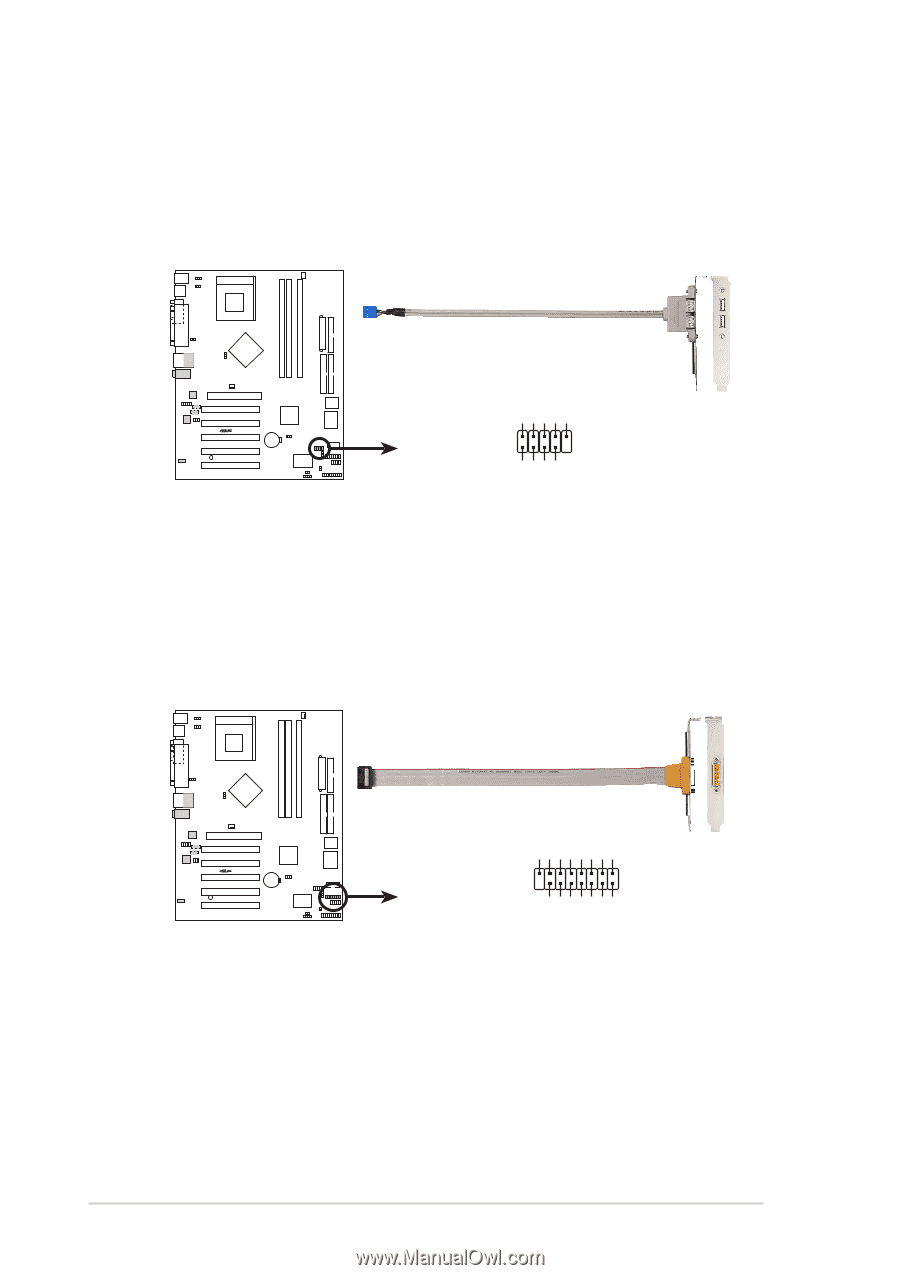
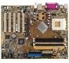
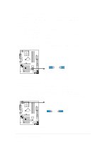
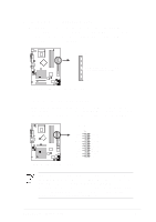
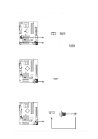
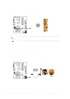
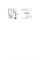
4. USB header (10-1 pin USB56) (optional) If the USB 2.0 port connectors on the back panel are inadequate, one USB header is available for four additional USB port connectors. Connect a 2-port USB connector set to a USB header and mount the USB bracket to an open slot in the chassis. ® A7N8X-X USB56 A7N8X-X USB 2.0 Header USB+5V USB_P5USB_P5+ GND MIDI_IN J2B2 J2CY MIDI_OUT J2CX J2B1 +5V +5V J1B2 J1CY GND GND J1CX J1B1 +5V ® 1 5. GAME/MIDI connector (16-1 pin GAME1) (optional) This connector supports a GAME/MIDI module. If your package came with the optional USB 2.0/GAME module, connect the GAME/MIDI cable to this connector. The GAME/MIDI port on the module connects a joystick or a game pad for playing games, and MIDI devices for playing or editing audio files. A7N8X-X GAME1 A7N8X-X Game Connector 1-14 Chapter 1: Motherboard Information USB+5V USB_P6USB_P6+ GND NC
-
 1
1 -
2
-
3
-
4
-
5
-
6
-
7
-
8
-
9
-
10
-
11
-
12
-
13
-
14
-
15
-
16
-
17
-
18
-
 19
19 -
 20
20 -
 21
21 -
 22
22 -
 23
23 -
 24
24 -
 25
25 -
 26
26 -
 27
27 -
 28
28 -
 29
29 -
30
-
31
-
32
-
33
-
34
-
35
-
36
-
37
-
38
-
39
-
40
-
41
-
42
-
43
-
44
-
45
-
46
-
47
-
48
-
49
-
50
-
51
-
52
-
53
-
54
-
55
-
56
-
57
-
58
-
59
-
60
 |
 |