Asus a7n8xx A7N8X-X User's Manual - Page 28
Asus a7n8xx Manual
 |
View all Asus a7n8xx manuals
Add to My Manuals
Save this manual to your list of manuals |
Page 28 highlights
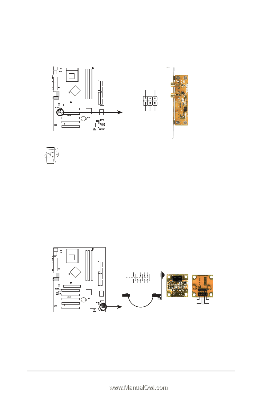
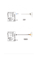
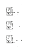
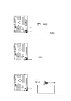
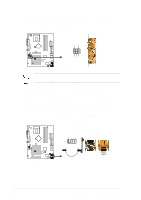
14. Digital Audio Connector (6 pin SPDIF1) (optional) This connector is for optional S/PDIF audio module that allows digital instead of analog sound input and output. GND GND 1 SPDIF1 +5V ® A7N8X-X A7N8X-X Digital Audio Connector When you input sound for S/PDIF IN, the LINE_OUT will output the sound. Mute LINE_OUT to impede sound output from S/PDIF IN. 15. Infrared Module connector (10-1 or 10-2 pin IR_CON1) (optional) These connectors support an optional wireless transmitting and receiving infrared module. The module mounts to a small opening on the system chassis that support this feature. You must also configure the UART2 Use As parameter in BIOS to set UART2 for use with IR. Use the ten pins as shown in Back View and connect a ribbon cable from the module to the motherboard SIR connector according to the pin definitions. IR_CON1 +5 V IRRX GND IRTX SPDIF_OUT SPDIF_IN Standard Infrared (SIR) Front View Back View SIR CIR NC GND NC CIRRX +5VSB ® A7N8X-X IRTX GND IRRX +5V (NC) A7N8X-X Infrared Connector 1-18 Chapter 1: Motherboard Information
-
 1
1 -
2
-
3
-
4
-
5
-
6
-
7
-
8
-
9
-
10
-
11
-
12
-
13
-
14
-
15
-
16
-
17
-
18
-
19
-
20
-
21
-
22
-
 23
23 -
 24
24 -
 25
25 -
 26
26 -
 27
27 -
 28
28 -
 29
29 -
 30
30 -
 31
31 -
 32
32 -
 33
33 -
34
-
35
-
36
-
37
-
38
-
39
-
40
-
41
-
42
-
43
-
44
-
45
-
46
-
47
-
48
-
49
-
50
-
51
-
52
-
53
-
54
-
55
-
56
-
57
-
58
-
59
-
60
 |
 |