Asus a7n8xx A7N8X-X User's Manual - Page 20
Asus a7n8xx Manual
 |
View all Asus a7n8xx manuals
Add to My Manuals
Save this manual to your list of manuals |
Page 20 highlights
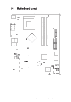
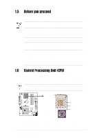
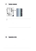
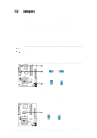
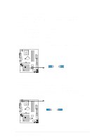
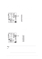
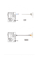
1.9 1. Jumpers USB device wake-up (3-pin USBPWR_12,USBPWR_34,USBPWR_56) Set these jumpers to +5V to wake up the computer from S1 sleep mode (CPU stopped, DRAM refreshed, system running in low power mode) using the connected USB devices. Set to +5VSB to wake up from S3 sleep mode (no power to CPU, DRAM in slow refresh, power supply in reduced power mode). Both jumpers are set to pins 1-2 (+5V) by default because not all computers have the appropriate power supply to support this feature. The USBPWR_12 and USBPWR_34 jumpers are for the rear USB port. USBPWR_56 is for the internal USB header that you can connect to the front USB ports. This feature requires a power supply that can provide at least 2A on the +5VSB lead when these jumpers are set to +5VSB. Otherwise, the system does not power up. The total current consumed must NOT exceed the power supply capability (+5VSB) whether under normal condition or in sleep mode. USBPWR_12 USBPWR_34 1 2 +5V (Default) 2 3 +5VSB This section describes and illustrates the jumpers on the motherboard. USBPWR_56 ® A7N8X-X 1 2 +5V (Default) 2 3 +5VSB A7N8X-X USB Device Wake Up 2. Central Processing Unit FSB (CPU_FSB) This jumper when set to 1-2 pins (default), enable support for Front Side Bus 400/333/266. When set to pins 2-3, it sets support for FSB 200 only. CPU_FSB 1 2 ® 2 3 FSB200 A7N8X-X FSB400/333/266 (Default) A7N8X-X CPU FSB Jumper Setting 1-10 Chapter 1: Motherboard Information
-
 1
1 -
2
-
3
-
4
-
5
-
6
-
7
-
8
-
9
-
10
-
11
-
12
-
13
-
14
-
 15
15 -
 16
16 -
 17
17 -
 18
18 -
 19
19 -
 20
20 -
 21
21 -
 22
22 -
 23
23 -
 24
24 -
 25
25 -
26
-
27
-
28
-
29
-
30
-
31
-
32
-
33
-
34
-
35
-
36
-
37
-
38
-
39
-
40
-
41
-
42
-
43
-
44
-
45
-
46
-
47
-
48
-
49
-
50
-
51
-
52
-
53
-
54
-
55
-
56
-
57
-
58
-
59
-
60
 |
 |