Behringer AT108 Manual - Page 7
Audio Connections
 |
View all Behringer AT108 manuals
Add to My Manuals
Save this manual to your list of manuals |
Page 7 highlights
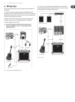
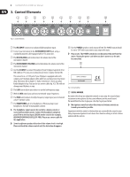
7 ULTRACOUSTIC AT108 User Manual 4. Audio Connections Except for the microphone input, the inputs and outputs are laid out as 1/4" connectors. More information about the connectors can be found in chapter 5, "Specifications." Please refer to Fig. 2.1 and 2.2 to learn about hooking up your amp. ◊ Please keep in mind that all the equipment has to be grounded at all times. For your own protection, never change or disable the grounding on your equipment or on the cables! The unit shall always be connected to the mains socket outlet with a protective earthing connection. Unbalanced ¼" TS connector strain relief clamp sleeve tip Balanced use with XLR connectors 21 3 input 1 = ground/shield 2 = hot (+ve) 3 = cold (-ve) 12 3 output For unbalanced use, pin 1 and pin 3 have to be bridged Fig. 4.3: XLR connections sleeve (ground/shield) tip (signal) Fig. 4.1: 1/4" TS plug for the INSTRUMENT INPUT (mono) ¼" TRS headphones connector strain relief clamp sleeve ring tip sleeve tip Fig. 4.4: Stereo adapter cable sleeve tip Fig. 4.5: Mono adapter cable sleeve tip sleeve tip sleeve ground/shield ring right signal tip left signal Fig. 4.2: 1/4" TRS for headphones or CD input
-
 1
1 -
 2
2 -
 3
3 -
 4
4 -
 5
5 -
 6
6 -
 7
7 -
 8
8 -
 9
9
 |
 |
