Behringer B-CONTROL DEEJAY BCD2000 Manual - Page 12
Asio Or Wdm/mme² - drivers
 |
View all Behringer B-CONTROL DEEJAY BCD2000 manuals
Add to My Manuals
Save this manual to your list of manuals |
Page 12 highlights
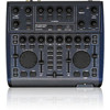
B-CONTROL DEEJAY BCD2000 5.3 Expanded setup Even though the B-DJ system can do without external drives and media, you can expand this controller software setup by adding a CD player (which you maybe already have) or two turntables. In this case, you can integrate the analog signal into the software mixer and process it with all real-time functions of the decks (such as EQ, cut-off filter, effects, fader, crossfader, VU meters, etc). Operating external devices is as intuitive as internal mixing. 5.4 Signal routing The USB interface allows you to record and play back four audio signals at the same time. The signal routing is determined by the settings of the B-DJ software, the control panel and the button positions. The signal routing also depends on the selected driver (ASIO or WDM/MME). 5.4.1 Routing options with ASIO driver B-DJ Mode: If “B-DJ” is selected in the GLOBAL MODE of the control panel, you can only select the input signals. The assignment of the outputs is fixed. Output 1-2 always provides the MASTER OUT signal, while the stereo headphone mix is assigned to output 3-4. The headphones mix is the same as the master signal, if MASTER OUT has been activated too. Fig. 5.3: Audio routing in B-DJ mode (ASIO driver) Advanced Mode: In Advanced Mode all ASIO parameters can be set. Select the input source for channel IN A (CH 1-2, Mic or Phono A) in the control panel. Select the input source for IN B (CH 3-4, Phono or Line) with the PHONO/LINE switch on the rear of the BCD2000. The playback channels CH 1-2 or CH 3-4 for the main outputs and the headphones connector are also selected in the control panel (MASTER OUT or PHONES OUT field respectively). Fig. 5.2: Expanding the standard setup In this setup, the standard setup shown in fig. 5.1 is expanded by adding two turntables and a microphone. The connection to the computer and the other peripheral devices is the same as in example 1. Connect the outputs of the turntables to inputs A and B. To use input B, set the PHONO/LINE switch to position “PHONO”. Alternatively, you can connect a CD player to input B. In this case, the PHONO/LINE switch must be set to “LINE”. Press the input source button to activate the inputs. You can manage up to four signal sources at the same time by switching the two channels between the analog source and the software signal. The MIC input with its XLR connector allows you to connect a microphone. The MIC LEVEL control in the MIC INPUT section determines the volume of the microphone signal. Use the ON AIR switch to activate the microphone channel. The clip LED illuminates as soon as the input signal’s level is too high and could possibly cause audible distortion. If this happens, turn the MIC LEVEL control to the left until the LED does not light up anymore. ANALOG INPUT A overrides the microphone channel. When this button is pressed, you cannot use the microphone. Fig. 5.4: Audio routing in Advanced Mode (ASIO) 12 5. OPERATION
-
 1
1 -
2
-
3
-
4
-
5
-
6
-
 7
7 -
 8
8 -
 9
9 -
 10
10 -
 11
11 -
 12
12 -
 13
13 -
 14
14 -
 15
15 -
 16
16 -
 17
17
 |
 |
