Behringer EUROPOWER PMP960M Manual - Page 10
Loudspeaker connection
 |
View all Behringer EUROPOWER PMP960M manuals
Add to My Manuals
Save this manual to your list of manuals |
Page 10 highlights
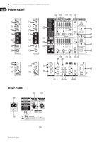
10 EUROPOWER PMP1680S/PMP980S/PMP960M User Manual ¼" TS footswitch connector strain relief clamp sleeve tip sleeve pole 1/ground Please be sure to only use professional locking-style speaker cables (type NL4FC). Please check the pin connections of your loudspeakers and cables depending on the EUROPOWER speaker output you choose. EUROPOWER PMP980S/PMP1680S OUPUT A 1+ 1- 2+ 2- MAIN L POS NEG - - MON POS NEG - - OUTPUT B - - POS NEG OUTPUT B 1+ 1- 2+ 2- MAIN R POS NEG - - MONO POS NEG - - BRIDGE POS - NEG - tip pole 2 EUROPOWER PMP960M OUTPUT A 1+ 1- 2+ 2- The footswitch connects both poles momentarily MAIN MONO POS NEG - - MON POS NEG - - Fig. 4.4: ¼" TS connector for footswitch BRIDGE - - - - ◊ Please use a dual footswitch for the PMP980S/PMP1680S, so that you OUTPUT B 1+ 1- 2+ 2- can enable/disable FX 1 and FX 2 independently of each other. In this MAIN MONO POS NEG - - case, the tip of the ¼" plug controls FX 1, and the ring FX 2. MAIN POS NEG - - BRIDGE POS - NEG - Tab 4.1: Pin connections of loudspeaker connectors tip tip sleeve shield sleeve OUTPUT B OUTPUT B Fig. 4.5: RCA cable 1+ 1+ 4.3 Loudspeaker connection Your PMP mixer is equipped with high-quality twist-lock professional style loudspeaker connectors, which ensure safe and trouble-free operation. This connector was especially developed for high-power loudspeakers. Once it is plugged in, it safely locks into position and cannot be accidentally disengaged. It prevents the occurrence of electrical shock and ensures the correct polarity. Each of the connectors carries only the assigned single signal (see tab. 4.1/fig. 4.7 and the information on the rear panel of the power mixer). Professional speaker connector (compatible with Neutrik Speakon connectors) 8 Ω 1- 1- 4 Ω BRIDGE 1+ 2+ 8 Ω 4 Ω 16 Ω 8 Ω Fig. 4.7: Connector assignment 1+ 1+ 2- 1- 1- 2- 2+ front view 2+ rear view Fig. 4.6: Professional twist-lock style connector
-
 1
1 -
2
-
3
-
4
-
 5
5 -
 6
6 -
 7
7 -
 8
8 -
 9
9 -
 10
10 -
 11
11 -
 12
12 -
 13
13 -
 14
14 -
 15
15 -
16
 |
 |
