Behringer ULTRAGRAPH PRO FBQ3102 Manual - Page 7
Rear panel, Additional FBQ6200 control elements
 |
View all Behringer ULTRAGRAPH PRO FBQ3102 manuals
Add to My Manuals
Save this manual to your list of manuals |
Page 7 highlights
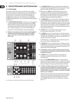
7 ULTRAGRAPH PRO FBQ6200/FBQ3102/FBQ1502 User Manual 2.2 Rear panel (14) (10) (15) (16) (17) (11) (12) (13) Fig. 2.3: Connectors at the rear of the FBQ3102 Fig. 2.2: Control elements and important information on the rear of the FBQ3102 (10) The POWER switch powers up your ULTRAGRAPH PRO. The POWER switch should always be in the "Off" position when you are about to connect your FBQ to the mains. To disconnect the unit from the mains, pull out the main cord plug. When installing the product, ensure that the plug is easily accessible. If mounting in a rack, ensure that the mains can be easily disconnected by a plug or by an all-pole disconnect switch on or near the rack. ◊ Please keep in mind: The POWER switch does not entirely separate the unit from the mains. Please disconnect the power cord from the mains if you will not be using your FBQ for longer periods of time. FBQ1502's power switch is located at the front. (11) The connection to the mains is done via a standard IEC connector. A matching cable is included. (12) FUSE COMPARTMENT / VOLTAGE SELECTION. Before connecting the unit to a power outlet, please make sure that the selected voltage matches your local voltage. When replacing fuses, please make sure that you always use fuses of the same type. Some units allow for switching between 230 V and 120 V. Please note: when connecting a unit intended for the European market to a 120 V power outlet, you must also replace the factory fuse with a higher-value fuse. (13) SERIAL NUMBER. Please take a few minutes and send to us a completely filled out warranty card within 14 days of the original date of purchase. Otherwise, warranty claims may be rendered invalid. Or fill out the warranty information online at behringer.com. (14) INPUT. These are the audio inputs of the FBQ3102. All three equalizers in the series feature the same input and output connectors in the form of balanced ¼" TRS and XLR connectors. (15) OUTPUT. These are the audio outputs. The ¼" connectors and their respective XLR connectors are wired in parallel. (16) SUB OUT. This balanced XLR connector provides the output signal for your subwoofer. A summed up mono signal for the subwoofer is provided here. Please connect the subwoofer amplifier's input to this connector. (17) Use the X-OVER FREQ control to select the desired crossover frequency for the subwoofer. ◊ The bandwidth limitation enacted through the high-pass filter (LOW CUT) also affects the frequency response of the subwoofer output. 2.3 Additional FBQ6200 control elements 2.3.1 Limiter One of the FBQ6200's outstanding features is its integrated limiter. A limiter is a device that protects your loudspeakers and other equipment connected to your FBQ6200 (or your recordings) from overdriving and the signal distortion associated. ◊ Please take into consideration that when you increase the presence of multiple frequency bands, the overall signal level increases substantially as well. The limiter will process very quickly in such situations. This can be avoided by performing signal corrections by lowering certain frequency ranges instead of increasing others. To produce creative sound effects, you can also purposely "force" the peak limiter into action.
-
 1
1 -
 2
2 -
 3
3 -
 4
4 -
 5
5 -
 6
6 -
 7
7 -
 8
8 -
 9
9 -
 10
10 -
 11
11 -
 12
12 -
13
-
14
-
15
-
16
 |
 |
