Biostar G965 MICRO 775 MANUAL - Page 18
JUSB2/JUSB3/JUSB4: Headers for USB 2.0 Ports at Front Panel, JAUDIOF1: Front Panel Audio Header,
 |
View all Biostar G965 MICRO 775 manuals
Add to My Manuals
Save this manual to your list of manuals |
Page 18 highlights
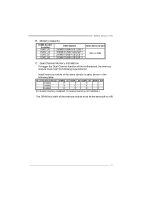
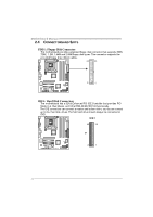
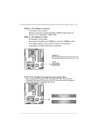
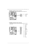
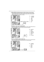
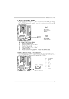
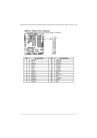
Motherboard Manual JUSB2/JUSB3/JUSB4: He ade rs for USB 2.0 Ports at Front Panel This motherboard prov ides 3 USB 2.0 headers, which allows user to connect additional USB cable on the PC front panel, and also can be connected with internal USB dev ices, like USB card reader. JUSB 2/JU SB 4/ JUS B3 9 1 Pin Assignment 1 +5V (fused) 2 +5V (fused) 3 USB4 USB5 USB+ 6 USB+ 7 Ground 8 Ground 9 Key 10 NC 10 2 JAUDIO F1: Front Panel Audio Heade r This header allows user to connect the front audio output cable with the PC f ront panel. It will disable the output on back panel audio connectors. 2 10 Pin Assignment 1 Mic in 2 Ground 3 Mic power 4 Audio power 5 Right line out 6 Right line out 7 Reserved 8 Key 9 Left line ou 10 LFT Line Out 1 9 JCDIN1: CD-RO M Audio-in Connector This connector allows user to connect the audio source f rom the v ariaty dev ices, like CD-ROM, DVD-ROM, PCI sound card, PCI TV turner card etc.. 4 1 Pin Assignment 1 Left Channel Input 2 Ground 3 Ground 4 Right Channel Input 16
-
 1
1 -
2
-
3
-
4
-
5
-
6
-
7
-
8
-
9
-
10
-
11
-
12
-
 13
13 -
 14
14 -
 15
15 -
 16
16 -
 17
17 -
 18
18 -
 19
19 -
 20
20 -
 21
21 -
 22
22 -
 23
23 -
24
-
25
-
26
-
27
-
28
-
29
-
30
-
31
-
32
-
33
-
34
-
35
-
36
-
37
-
38
-
39
-
40
-
41
-
42
-
43
-
44
-
45
-
46
-
47
-
48
-
49
-
50
-
51
 |
 |
