Biostar G965 MICRO 775 MANUAL - Page 20
JSPDIF_O UT: Digital Audio out Connectors, JSPDIF_IN: Digital Audio in Connectors optional, JCI1:
 |
View all Biostar G965 MICRO 775 manuals
Add to My Manuals
Save this manual to your list of manuals |
Page 20 highlights
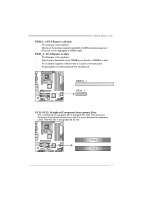
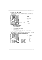
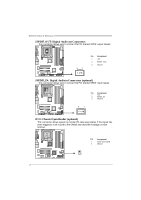
Motherboard Manual JSPDIF_O UT: Digital Audio out Conne ctors This connector allows user to connect the PCI bracket SPDIF output header. 3 1 Pin Assignment 1 +5V 2 SPDIF_OUT 3 Ground JSPDIF_IN: Digital Audio in Conne ctors (optional) This connector allows user to connect the PCI bracket SPDIF input header. Pin Assignment 1 +5V 2 SPDIF_IN 3 Ground 3 1 JCI1: Chassis O pen Heade r (optional) This connector allows system to monitor PC case open status. If the signal has been triggered, it will record to the CMOS and show the message on next boot-up. Pin Assignment 1 Case open signal 2 Ground 1 2 18
-
 1
1 -
2
-
3
-
4
-
5
-
6
-
7
-
8
-
9
-
10
-
11
-
12
-
13
-
14
-
 15
15 -
 16
16 -
 17
17 -
 18
18 -
 19
19 -
 20
20 -
 21
21 -
 22
22 -
 23
23 -
 24
24 -
 25
25 -
26
-
27
-
28
-
29
-
30
-
31
-
32
-
33
-
34
-
35
-
36
-
37
-
38
-
39
-
40
-
41
-
42
-
43
-
44
-
45
-
46
-
47
-
48
-
49
-
50
-
51
 |
 |

Motherboard Manual
18
JSPDIF_O UT: Digital Audio out Connectors
This connector allows user to connect the PCI bracket SPDIF output header.
Pin
Assignment
1
+5V
2
SPDIF_OUT
1
3
3
Ground
JSPDIF_IN: Digital Audio in Connectors (optional)
This connector allows user to connect the PCI bracket SPDIF input header.
Pin
Assignment
1
+5V
2
SPDIF_IN
1
3
3
Ground
JCI1: Chassis O pen Header (optional)
This connector allows system to monitor PC case open status. If the signal has
been triggered, it will record to the CMOS and show the message on next
boot-up.
Pin
Assignment
1
Case open signal
1
2
2
Ground