Biostar M7VIG PRO D M7VIG Pro D user's manual
Biostar M7VIG PRO D Manual
 |
View all Biostar M7VIG PRO D manuals
Add to My Manuals
Save this manual to your list of manuals |
Biostar M7VIG PRO D manual content summary:
- Biostar M7VIG PRO D | M7VIG Pro D user's manual - Page 1
energy and, if not installed and used in accordance with the instructions, may cause harmful interference to radio communications. There is no guarantee vendor's approval in writing. The content of this user's manual is subject to be changed without notice and we will not be responsible for any mistakes - Biostar M7VIG PRO D | M7VIG Pro D user's manual - Page 2
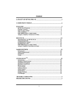
Headers, Connectors & Slots 6 DEUTSCH 13 Spezifikationen von M7VIG Pro-D 13 Verpackungsinhalt 14 Einstellung der Jumper 14 Installation der CPU 15 DDR-DIMM-Modules: DDR1/ DDR2 16 Jumpers, 41 Screensaver ...42 Display Settings...43 File Manager...44 TROUBLE SHOOTING 1 PROBLEMLÖSUNG 2 ii - Biostar M7VIG PRO D | M7VIG Pro D user's manual - Page 3
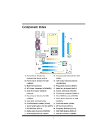
Layout of M7VIG Pro-D ※NOTE: ●represents the first pin. 1 - Biostar M7VIG PRO D | M7VIG Pro D user's manual - Page 4
Connector (FDD1) D. ATX Power Connector (JATXPWER1) P. Wake On LAN Header (JWOL1) E. Game Port Header (JGAME1) Q. System FAN Header Frequency Selection (JCLK1) K. Digital Audio Connector (JSPDIF1) X. DDR DIMM Modules (DDR1-2) L. Front Audio Header (JF_AUDIO) Y. CPU Fan Connector (JCFAN1) 2 - Biostar M7VIG PRO D | M7VIG Pro D user's manual - Page 5
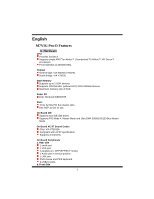
English M7VIG Pro-D Features A. Hardware CPU Provides Socket A. Supports single AMD® for Athlon™ (Thunderbird™)/ Athlon™ XP/ Duron™ processors. Front Side Bus at 200/266 MHz. Chipset North Bridge: VIA KM266 (VT8375). South Bridge: VIA VT8235. Main Memory Supports up to 2 DDR devices. Supports 200/ - Biostar M7VIG PRO D | M7VIG Pro D user's manual - Page 6
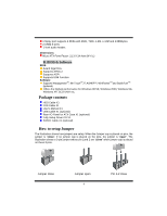
.4cm (W X L) B. BIOS & Software BIOS Award legal Bios. Supports APM1.2. Supports ACPI. Supports USB Function. Software Supports WarpspeederTM, 9th TouchTM, FLASHER™, WinFlasherTM and StudioFun!TM (optional). Offers the highest performance for Windows 98 SE, Windows 2000, Windows Me, Windows XP, SCO - Biostar M7VIG PRO D | M7VIG Pro D user's manual - Page 7
lever sideways away from the socket and then raise the lever up to a 90-degree angle. Step2: Look for the white dot/cut edge. The white dot/cut edge should point towards the lever pivot. The CPU will fit only in the correct orientation. Step3: Hold the CPU down firmly, and then close - Biostar M7VIG PRO D | M7VIG Pro D user's manual - Page 8
1GB DIMM Module (184 pin) Total Memory Size with Unbuffered DIMMs DIMM Socket Location DDR1 DDR2 DDR Module 64MB/128MB/256MB/512MB/1GB *1 64MB/128MB/ motherboard provides a standard floppy disk connector that supports 360K, 720K, 1.2M, 1.44M and 2.88M floppy disk types. This connector supports - Biostar M7VIG PRO D | M7VIG Pro D user's manual - Page 9
cards. This PCI slot is designated as 32 bits. Accelerated Graphics Port Slot: AGP1 Your monitor will attach directly to that video card. This motherboard supports video cards for PCI slots, but it is also equipped with an Accelerated Graphics Port (AGP). An AGP card will take advantage of AGP - Biostar M7VIG PRO D | M7VIG Pro D user's manual - Page 10
Wake On LAN Header: JWOL1 Pin 1 3 1 JWOL1 2 3 Assignment +5V Standby Ground Wake up Power Connectors: PS/2 Keyboard are powered with +5V standby voltage Note: In order to support this function "Power-on system via keyboard and mouse, "JKBV1" jumper cap should be placed on pin 2-3. - Biostar M7VIG PRO D | M7VIG Pro D user's manual - Page 11
JUSBLAN1 port powered with standby voltage of 5V Note: In order to support this function "Power-on the system via USB device", "JUSBV1/JUSBV2/ Data The following procedures are for resetting the BIOS password. It is important to follow these instructions closely. ※ Clear CMOS Procedures: 1. Remove - Biostar M7VIG PRO D | M7VIG Pro D user's manual - Page 12
5. Power on AC. 6. Reset your desired password or clear the CMOS data. Case Open Connector: JCI1 Pin 1 1 JCI1 2 Assignment Case Open Signal Ground CD-ROM Audio-In Header: JCDIN1 4 1 JCDIN1 Pin Assignment 1 Left Channel Input 2 Ground 3 Ground 4 Right Channel Input Front Panel - Biostar M7VIG PRO D | M7VIG Pro D user's manual - Page 13
CNR Codec/ Onboard Selection: JCODECSEL JCODECSEL 3 1 Pin 1-2 Close 3 1 Pin 2-3 Close Assignment Onboard Codec is used (default) CNR Codec is used CPU Frequency Selection: JCLK1 JCLK1 1 Pin 1-2 Close 1 Pin 1-2 Open Assignment 100 MHz 133 MHz Game Port Header: JGAME1 15 1 16 2 JGAME1 Pin - Biostar M7VIG PRO D | M7VIG Pro D user's manual - Page 14
Back Panel Connectors JKBMS1 PS/2 Mouse JUSB4 PS/2 USB Keyboard JPRNT1 Parallel JUSBLAN1 LAN Line In Speaker Out Mic In COM1 JCOM1 VGA1 JVGA1 USB JAUDIO 12 - Biostar M7VIG PRO D | M7VIG Pro D user's manual - Page 15
Deutsch Spezifikationen von M7VIG Pro-D A. Hardware CPU Unterstützung für Sockel A. Unterstützung für die AMD® Athlon/(ThunderbirdTM) /AthlonTM XP/DuronTM Prozessoren FSB mit 200/266MHz. Chipsatz Northbridge: VIA KM266.(VT8375) Southbridge: VIA KT8235. Hauptspeicher Unterstützung für 2 DDR Geräte. - Biostar M7VIG PRO D | M7VIG Pro D user's manual - Page 16
2.0-Ports. 1 Front -Audio-Header. Abmessungen Micro ATX Form-Factor: 21.3 X 24.4cm (W X L) B. BIOS & Software BIOS Award legal Bios. Unterstützung für APM1 für die am meisten verbreiteten Betriebsysteme wie Windows 98SE, Windows 2000, Windows ME, Windows XP und SCO UNIX usw. Verpackungsinhalt HDD - Biostar M7VIG PRO D | M7VIG Pro D user's manual - Page 17
nur, wenn sie richtig ausgerichtet ist. Schritt 3: Drücken Sie die CPU fest in den Sockel und schließen Sie den Hebel. Schritt 4: Stecken Sie Ihren CPU-Lüfter auf die CPU. Schließen Sie die Stromversorgungsstecker für CPU-Lüfter an JCFAN1 an. Dann beenden Sie die Installation. Schritt 1 Schritt - Biostar M7VIG PRO D | M7VIG Pro D user's manual - Page 18
in den Slot, bis die seitlichen Clips zuschnappen und das Modul fest sitzt. Jumpers, Headers, Anschlüsse & Slots Diskettenanschluss: FDD1 Das Motherboard enthält einen standardmäßigen Diskettenanschluss, der 360K-, 720K-, 1.2M-, 1.44M- und 2.88M-Disketten unterstützt. Dieser Anschluss unterstützt - Biostar M7VIG PRO D | M7VIG Pro D user's manual - Page 19
PCI-Slot ist für 32 bits vorgesehen. Accelerated Graphics Port Slot: AGP1 Ihr Monitor wird direkt an die Grafikkarte angeschlossen. Dieses Motherboard unterstützt Grafikkarten für PCI-Slots, aber es ist auch mit einem Accelerated Graphics Port ausgestattet. AGP-Karten verwenden die AGP-Technologie - Biostar M7VIG PRO D | M7VIG Pro D user's manual - Page 20
: JUSB3 Pin Belegung 2 10 1 +5V(geschmelzt) 1 9 3 USBP4- 5 USBP4+ JUSB3 7 Masse 9 Schlüsse IRRX Pin Belegung 2 +5V(geschmelzt) 4 USBP5- 6 USBP5+ 8 Masse 10 Kein Wake On LAN Header: JWOL1 Pin 1 3 1 JWOL1 2 3 Belegung +5V reservierte Spannung Masse Aufwecken 18 - Biostar M7VIG PRO D | M7VIG Pro D user's manual - Page 21
Auswahl von Stromsmodi für Tastatur/ Maus: JKBV1 JKBV1 Belegung Beschreibung 1 3 +5V +5V für Tastatur und Maus Pin 1-2 gescglossen 1 3 Pin 2-3 geschlossen +5V reservierte Spannung Durch +5V reservierte Sapnnung für PS/2-Tastatur und PS/2-Maus zum Erwecken von dem System Anmerkung: Um die - Biostar M7VIG PRO D | M7VIG Pro D user's manual - Page 22
Default) CMOS-Daten Löschen Die folgende Schritte leiten Sie, das Kennwort für BIOS-System zurückzusetzen. Es ist wichtig, die Anweisung zu folgen. ※ Proze Pin 1 Belegung 1 Gehäuse Öffnen Signal JC1 2 Masse CD-ROM Audio-In Header: JCDIN1 4 1 JCDIN1 Pin Belegung 1 Link-Kanal Eingabe 2 - Biostar M7VIG PRO D | M7VIG Pro D user's manual - Page 23
10 1 9 JF_AUDIO Pin Belegung Pin Belegung 1 Mikrofon-Eingabe/Zentrum 2 Masse 3 Mikrofon-Betriebsspannung/B ass 4 Audio-Betriebsspannung 5 Audio-Signal des rechten Audio-Signal des rechten Kanals zur Vorderseite / Kanals zurVorderseite / Lautsprecher-Signal des 6 Lautsprecher-Signal - Biostar M7VIG PRO D | M7VIG Pro D user's manual - Page 24
CPU Frequenz Auswahl: JCLK1 JCLK1 1 Pin 1-2 geschlossen 1 Pin 1-2 geööffnet Game Header: JGAME1 15 1 Beschreibung 100MHZ 133MHz 16 sse für die Rückwand JKBMS1 PS/2Maus JUSB4 PS/2- USB Tastatur JPRNT1 Parallel JUSBLAN1 LAN Line In Speaker Out Mic In COM1 JCOM1 VGA1 JVGA1 USB JAUDIO 22 - Biostar M7VIG PRO D | M7VIG Pro D user's manual - Page 25
about BIOS model and chipsets. In addition, the frequency status of CPU, memory, AGP and PCI along with the CPU speed are Support: Windows 98 SE, Windows Me, Windows 2000, Windows XP DirectX: DirectX 8.1 or above. (The Windows XP operating system includes DirectX 8.1. If you use Windows XP - Biostar M7VIG PRO D | M7VIG Pro D user's manual - Page 26
Installation 1. Execute the setup execution file, and then the following dialog will pop up. Please click "Next" button and follow the default procedure to install. 2. When you see the following dialog in setup procedure, it means setup is completed. If the "Launch the WarpSpeeder Tray Utility" - Biostar M7VIG PRO D | M7VIG Pro D user's manual - Page 27
Usage The following figures are just only for reference, the screen printed in this user manual will change according to your motherboard on hand. [WarpSpeeder™] includes 1 tray icon and 5 panels: 1. Tray Icon: Whenever the Tray Icon utility is launched, it will display a little tray icon on the - Biostar M7VIG PRO D | M7VIG Pro D user's manual - Page 28
[ WarpSpeeder™ ] utility will be invoked. Please refer do the following figure; the utility's first window you will see is Main Panel. Main Panel contains features as follows: a. Display the CPU Speed, CPU external clock, Memory clock, AGP clock, and PCI clock information. b. Contains About, Voltage - Biostar M7VIG PRO D | M7VIG Pro D user's manual - Page 29
button will be highlighted and the Voltage Panel will slide out to up as the following figure. In this panel, you can decide to increase CPU core voltage and Memory voltage or not. The default setting is "No". If you want to get the best performance of overclocking, we recommend you - Biostar M7VIG PRO D | M7VIG Pro D user's manual - Page 30
4. Overclock Panel Click the Overclock button in Main Panel, the button will be highlighted and the Overclock Panel will slide out to left as the following figure. 28 - Biostar M7VIG PRO D | M7VIG Pro D user's manual - Page 31
3MHz button", "-1MHz button", "+1MHz button", and "+3MHz button": provide user the ability to do real-time overclock adjustment. Warning: Manually overclock is potentially dangerous, especially when the overclocking percentage is over 110 %. We strongly recommend you verify every speed you overclock - Biostar M7VIG PRO D | M7VIG Pro D user's manual - Page 32
c. "Auto-overclock button": User can click this button and [ WarpSpeeder™ ] will set the best and stable performance and frequency automatically. [ WarpSpeeder™ ] utility will execute a series of testing until system fail. Then system will do fail-safe reboot by using Watchdog function. After reboot - Biostar M7VIG PRO D | M7VIG Pro D user's manual - Page 33
, you can get model name and detail information in hints of all the chipset that are related to overclocking. You can also get the mainboard's BIOS model and the Version number of [ WarpSpeeder™ ] utility. 31 - Biostar M7VIG PRO D | M7VIG Pro D user's manual - Page 34
hardware monitor features are controlled by several separate chipset, [ WarpSpeeder™ ] divide these features to separate panels. If one chipset is not on board, the correlative button in Main panel will be disabled, but will not interfere other panels' functions. This property can make [ WarpSpeeder - Biostar M7VIG PRO D | M7VIG Pro D user's manual - Page 35
"Room Theater" experience into life. It plays DVD, VCD, MP3, Audio CD and other multimedia. Furthermore, Users can take snapshots of video and flash disks and USB floppy disks. Hardware Requirements The supported hardware list of StudioFun! updates regularly. So please check the "hwreq.txt" located - Biostar M7VIG PRO D | M7VIG Pro D user's manual - Page 36
selecting "Cancel" will terminate the installation and reboot the machine. If Windows or GNU/Linux is the only OS installed on the hard disk with procedure will then probe for the type of mouse installed. The distribution currently supports PS/2, USB and Serial mice. In case of serial mouse you will - Biostar M7VIG PRO D | M7VIG Pro D user's manual - Page 37
StudioFun! Recover Where there is a MBR (Master Boot record) corruption, the "StudioFun Recover" will automatically probe the hard disk master boot record and find out the installed operating system(s). Once success, it will re-install the boot loader with correct options in the MBR. Please be noted - Biostar M7VIG PRO D | M7VIG Pro D user's manual - Page 38
After executing the boot up, you will see the main Desktop screen. The following section is a complete description of the Desktop application. Desktop This is the main shell of the StudioFun! software. It illustrates two main categories, one is the main "Media Control" part and the other is the " - Biostar M7VIG PRO D | M7VIG Pro D user's manual - Page 39
put in to the drive when the Desktop (StudioFun! shell) is up and running, otherwise, the control will simply glow to inform the user about a AUDIO present in the DVD/CD-ROM drive. 5. FILE This control will glow whenever a File CD (CDs with other media type files) is detected in a DVD - Biostar M7VIG PRO D | M7VIG Pro D user's manual - Page 40
2. Screensaver Clicking this icon will invoke the screensaver application. Refer to section 5.3 Screensaver for more details. 3. Display Settings Clicking this icon will invoke the application for changing the screen resolutions. Refer to section 5.4, Display Settings for more details. 4. File - Biostar M7VIG PRO D | M7VIG Pro D user's manual - Page 41
e. DVD/VCD menus (requires external plug-in) f. Audio and subtitle channel selection g. Closed Caption support h. Brightness, contrast, audio volume, hue, saturation adjusting requires hardware/driver support) i. Playlist j. Image snapshot k. Audio re-sampling l. Software de-interlacing algorithms - Biostar M7VIG PRO D | M7VIG Pro D user's manual - Page 42
Software Details 10 l. Windows Media Video 7 m. Motion JPEG • Remote Control Support. a. Infrared interface b. User-friendly • Usage of StudioFun! with CelomaChrome skin a. Select VCD button to play a VCD disc b. Select DVD button to play a DVD disc c. Select CDDA button to play a Audio CD d. Select - Biostar M7VIG PRO D | M7VIG Pro D user's manual - Page 43
m. Select "menu" button to use menu while playing DVD n. Select "control" button to adjust brightness / color o. Select "setup" button to modify the settings of the player p. Select "f.scr" button to show the video output of the player in full screen mode q. Select "snap" button to take a snapshot - Biostar M7VIG PRO D | M7VIG Pro D user's manual - Page 44
Screensaver Screensaver The xscreensaver daemon waits until the keyboard and mouse have been idle for a period, and then runs a graphics demo chosen at random. The demo is terminated as soon as there is any mouse or keyboard activity. The xscreensaver-demo program is the graphical user interface to - Biostar M7VIG PRO D | M7VIG Pro D user's manual - Page 45
2. Only one Screen Saver: When user chooses this option, screensaver displays only one graphics demo. 3. Blank Screen Only: When user chooses this option, screensaver only blanks the screen instead of displaying the graphics demo. 4. Disable Screen Saver: When user chooses this option, screensaver - Biostar M7VIG PRO D | M7VIG Pro D user's manual - Page 46
three resolutions. • 640x480 • 800x600 • 1024x768 The current resolution of the Display will be selected by default. It requires restart of the StudioFun! to reflect the changes made. File Manager Overview File manger is a utility to copy files from deferent devices to hard disk and vice versa. User - Biostar M7VIG PRO D | M7VIG Pro D user's manual - Page 47
45 - Biostar M7VIG PRO D | M7VIG Pro D user's manual - Page 48
Trouble Shooting PROBABLE SOLUTION No power to the system at all Power light don't * Make sure power cable is securely plugged in illuminate, fan inside power supply does not on. Indicator light on keyboard does not turn turn on * Replace cable * Contact technical support . board. Review - Biostar M7VIG PRO D | M7VIG Pro D user's manual - Page 49
Problemlösung MÖGLICHE URSACHE LÖSUNG Das System hat keine Spannungsversorgung. * Versichern Sie sich, dass das Stromkabel richtig Die Stromanzeige leuchtet nicht, der Lüfter im angebracht ist Inneren der eingeschaltet. Stromversorgung Tastaturleuchten sind wird nicht nicht an. * Ersetzen - Biostar M7VIG PRO D | M7VIG Pro D user's manual - Page 50
06/20/2003 3
-
 1
1 -
 2
2 -
 3
3 -
 4
4 -
 5
5 -
 6
6 -
 7
7 -
8
-
9
-
10
-
11
-
12
-
13
-
14
-
15
-
16
-
17
-
18
-
19
-
20
-
21
-
22
-
23
-
24
-
25
-
26
-
27
-
28
-
29
-
30
-
31
-
32
-
33
-
34
-
35
-
36
-
37
-
38
-
39
-
40
-
41
-
42
-
43
-
44
-
45
-
46
-
47
-
48
-
49
-
50
 |
 |

M
M
7
7
V
V
I
I
G
G
P
P
r
r
o
o
-
-
D
D
i
FCC Information and Copyright
This equipment has been tested and found to comply with the limits of a
Class B digital device, pursuant to Part 15 of the FCC Rules. These limits
are designed to provide reasonable protection against harmful
interference in a residential installation. This equipment generates, uses
and can radiate radio frequency energy and, if not installed and used in
accordance with the instructions, may cause harmful interference to radio
communications. There is no guarantee that interference will not occur in
a particular installation.
The vendor makes no representations or warranties with respect to the
contents here of and specially disclaims any implied
warranties
of
merchantability or fitness for any purpose. Further the vendor reserves
the right to revise this publication and to make changes to the contents
here of without obligation to notify any party beforehand.
Duplication of this publication, in part or in whole, is not allowed without
first obtaining the vendor’s approval in writing.
The content of this user’s manual is subject to be changed without notice
and we will not be responsible for any mistakes found in this user’s
manual. All the brand and product names are trademarks of their
respective companies.