Biostar M7VIG PRO D M7VIG Pro D user's manual - Page 11
Power Source Selection for USB: JUSBV1/ JUSBV2/ JUSBV3, Clear CMOS Jumper: JCMOS1 - bios
 |
View all Biostar M7VIG PRO D manuals
Add to My Manuals
Save this manual to your list of manuals |
Page 11 highlights
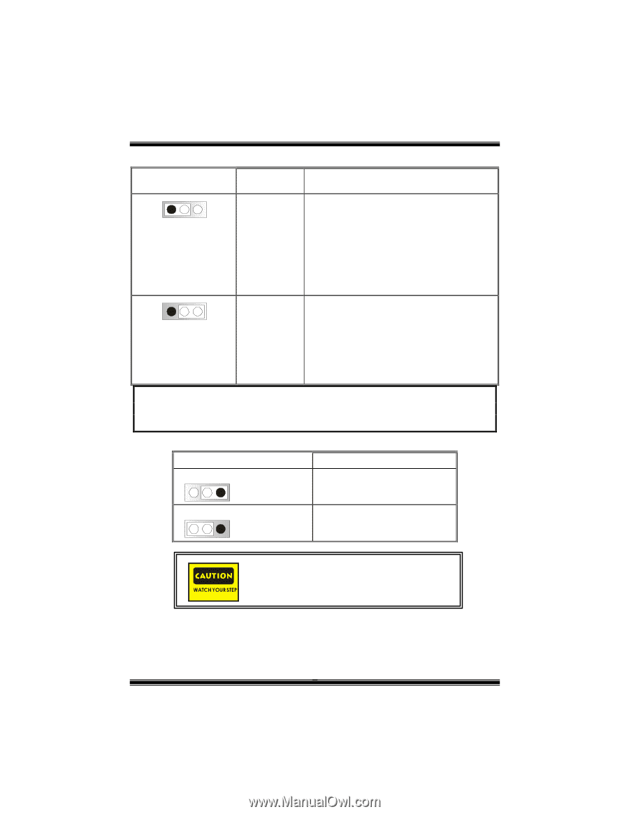
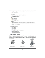
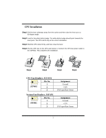
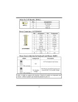
Power Source Selection for USB: JUSBV1/ JUSBV2/ JUSBV3 JUSBV1/ JUSBV2/ JUSBV3 Assignment Description 1 3 Pin 1-2 close JUSBV2: 5V for USB located at the JUSB4 port +5V JUSBV3: 5V for USB located at the JUSB3 port JUSBV1: 5V for USB located at the JUSBLAN1 port 1 3 Pin 2-3 close +5V Standby Voltage JUSBV2: JUSB4 port powered with standby voltage of 5V JUSBV3: JUSB3 port powered with standby voltage of 5V JUSBV1: JUSBLAN1 port powered with standby voltage of 5V Note: In order to support this function "Power-on the system via USB device", "JUSBV1/JUSBV2/JUSBV3" jumper cap should be placed on pin 2-3 respectively. Clear CMOS Jumper: JCMOS1 JCMOS1 3 1 Pin 1-2 Close 3 1 Pin 2-3 Close Assignment Normal Operation (default) Clear CMOS Data The following procedures are for resetting the BIOS password. It is important to follow these instructions closely. ※ Clear CMOS Procedures: 1. Remove AC power line. 2. Set the jumper to "Pin 2-3 close". 3. Wait for five seconds. 4. Set the jumper to "Pin 1-2 close". 9
-
 1
1 -
2
-
3
-
4
-
5
-
 6
6 -
 7
7 -
 8
8 -
 9
9 -
 10
10 -
 11
11 -
 12
12 -
 13
13 -
 14
14 -
 15
15 -
 16
16 -
17
-
18
-
19
-
20
-
21
-
22
-
23
-
24
-
25
-
26
-
27
-
28
-
29
-
30
-
31
-
32
-
33
-
34
-
35
-
36
-
37
-
38
-
39
-
40
-
41
-
42
-
43
-
44
-
45
-
46
-
47
-
48
-
49
-
50
 |
 |