Biostar M7VIG PRO D M7VIG Pro D user's manual - Page 10
Wake On LAN Header: JWOL1, Power Connectors: JATXPWER1, Power Source Selection for Keyboard
 |
View all Biostar M7VIG PRO D manuals
Add to My Manuals
Save this manual to your list of manuals |
Page 10 highlights
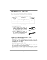
Wake On LAN Header: JWOL1 Pin 1 3 1 JWOL1 2 3 Assignment +5V Standby Ground Wake up Power Connectors: JATXPWER1 PIN Assignment PIN 20 10 1 +3.3V 11 2 +3.3V 12 3 Ground 13 4 +5V 14 5 Ground 15 11 1 6 +5V 16 7 Ground 17 JATXPWER1 8 PW_OK 18 9 Standby Voltage 19 +5V 10 +12V 20 Assignment +3.3V -12V Ground PS_ON Ground Ground Ground -5V +5V +5V Power Source Selection for Keyboard and Mouse: JKBV1 JKBV1 Assignment Description 1 +5V 3 Pin 1-2 close +5V for keyboard and mouse 1 3 Pin 2-3 close +5V Standby Voltage PS/2 Mouse and PS/2 Keyboard are powered with +5V standby voltage Note: In order to support this function "Power-on system via keyboard and mouse, "JKBV1" jumper cap should be placed on pin 2-3. 8
-
 1
1 -
2
-
3
-
4
-
 5
5 -
 6
6 -
 7
7 -
 8
8 -
 9
9 -
 10
10 -
 11
11 -
 12
12 -
 13
13 -
 14
14 -
 15
15 -
16
-
17
-
18
-
19
-
20
-
21
-
22
-
23
-
24
-
25
-
26
-
27
-
28
-
29
-
30
-
31
-
32
-
33
-
34
-
35
-
36
-
37
-
38
-
39
-
40
-
41
-
42
-
43
-
44
-
45
-
46
-
47
-
48
-
49
-
50
 |
 |
8
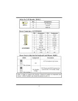
Wake On LAN Header: JWOL1
Pin
Assignment
1
+5V Standby
2
Ground
1
3
JWOL1
3
Wake up
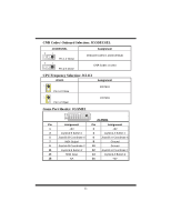
Power Connectors: JATXPWER1
PIN
Assignment
PIN
Assignment
1
+3.3V
11
+3.3V
2
+3.3V
12
-12V
3
Ground
13
Ground
4
+5V
14
PS_ON
5
Ground
15
Ground
6
+5V
16
Ground
7
Ground
17
Ground
8
PW_OK
18
-5V
9
Standby Voltage
+5V
19
+5V
10
1
20
11
JATXPWER1
10
+12V
20
+5V
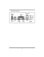
Power Source Selection for Keyboard and Mouse: JKBV1
JKBV1
Assignment
Description
1
3
Pin 1-2 close
+5V
+5V for keyboard and mouse
1
3
Pin 2-3 close
+5V Standby
Voltage
PS/2 Mouse and PS/2 Keyboard are
powered with +5V standby voltage
Note: In order to support this function “Power-on system via keyboard and
mouse, “JKBV1” jumper cap should be placed on pin 2-3.