Biostar N4SIE-A7 N4SIE-A7 BIOS guide
Biostar N4SIE-A7 Manual
 |
View all Biostar N4SIE-A7 manuals
Add to My Manuals
Save this manual to your list of manuals |
Biostar N4SIE-A7 manual content summary:
- Biostar N4SIE-A7 | N4SIE-A7 BIOS guide - Page 1
N4SIE-A7 BIOS Setup BIOS Setup 1 1 Main Menu ...3 2 Standard CMOS Features 6 3 Advanced BIOS Features 9 4 Advanced Chipset Features 13 5 Integrated Peripherals 17 6 Power Management Setup 22 7 PnP/PCI Configurations 25 8 PC Health Status ...27 i - Biostar N4SIE-A7 | N4SIE-A7 BIOS guide - Page 2
this manual is intended to guide you through the process of configuring your system using Setup. Plug and Play Support These AWARD BIOS supports the Plug and Play Version 1.0A specification. ESCD (Extended System Configuration Data) write is supported. EPA Green PC Support This AWARD BIOS supports - Biostar N4SIE-A7 | N4SIE-A7 BIOS guide - Page 3
N4SIE-A7 PCI Bus Support This AWARD BIOS also supports Version 2.1 of the Intel PCI (Peripheral Component Interconnect) local bus specification. DRAM Support DDR SDRAM (Double Data Rate Synchronous DRAM) are supported. Supported CPUs This AWARD BIOS supports the Intel CPU. Using Setup In general, - Biostar N4SIE-A7 | N4SIE-A7 BIOS guide - Page 4
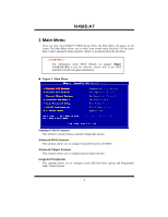
N4SIE-A7 1 Main Menu Once you enter Award BIOS™ CMOS Setup Utility, the Main Menu will appear on the !! WARNING !! The information about BIOS defaults on manual (Figure 1,2,3,4,5,6,7,8,9) is just for reference, please refer to the BIOS installed on board, for update information. Figure 1. Main Menu - Biostar N4SIE-A7 | N4SIE-A7 BIOS guide - Page 5
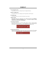
N4SIE-A7 Power Management Setup This submenu allows you to configure the power management the voltage and clock may cause the CPU or M/B damage!) Load Optimized Defaults This selection allows you to reload the BIOS when the system is having problems particularly with the boot sequence. These - Biostar N4SIE-A7 | N4SIE-A7 BIOS guide - Page 6
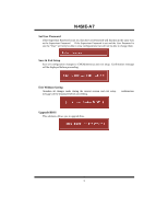
N4SIE-A7 Set User Password If the Supervisor Password is not set, then the User but will not be able to change them. Save & Exit Setup Save all configuration changes to CMOS(memory) and exit setup. Confirmation message will be displayed before proceeding. Exit Without Saving Abandon all changes made - Biostar N4SIE-A7 | N4SIE-A7 BIOS guide - Page 7
N4SIE-A7 2 Standard CMOS Features The items in Standard CMOS Setup Menu are divided into 10 categories. Each category includes no, one or more than one setup - Biostar N4SIE-A7 | N4SIE-A7 BIOS guide - Page 8
N4SIE-A7 Main Menu Selections This table shows the selections that you can make on the Main Menu. Item Options Description Date mm : dd : yy Set the - Biostar N4SIE-A7 | N4SIE-A7 BIOS guide - Page 9
N4SIE-A7 Item Halt On Base Memory Extended Memory Total Memory Options All Errors No Errors All, but Keyboard All, but Diskette All, but Disk/ Key N/A N/A N/A Description Select the situation in which you want the BIOS to stop the POST process and notify you. Displays the amount of conventional - Biostar N4SIE-A7 | N4SIE-A7 BIOS guide - Page 10
N4SIE-A7 3 Advanced BIOS Features Figure 3. Advanced BIOS Setup Boot Seq & Floppy Setup Hard Disk Boot Priority These BIOS attempt to load the Floppy, LS120, HDD-0, SCSI, CDROM, HDD-1, HDD-2, HDD-3, ZIP100, LAN, Disabled. Swap Floppy Drive For systems with two floppy drives, this option allows - Biostar N4SIE-A7 | N4SIE-A7 BIOS guide - Page 11
N4SIE-A7 Cache Setup These BIOS attempt to load the operating system from the device in the sequence selected in these items. CPU L1&L2 Cache Depending on the CPU/chipset in use, you may be able to increase memory access time with this option. Enabled (default) Enable cache. Disabled - Biostar N4SIE-A7 | N4SIE-A7 BIOS guide - Page 12
N4SIE-A7 Virus Warning This option allows you to choose the Virus Warning feature that is used to protect the IDE Hard Disk boot sector. If this function is enabled and an attempt is made to write to the boot sector, BIOS will display a warning message on the screen and sound an alarm beep - Biostar N4SIE-A7 | N4SIE-A7 BIOS guide - Page 13
N4SIE-A7 Security Option This option will enable only individuals with passwords to (default), Disabled. MPS Version Control For OS The BIOS supports version 1.1 and 1.4 of the Intel multiprocessor specification.Select version supported by the operation system running on this computer. The - Biostar N4SIE-A7 | N4SIE-A7 BIOS guide - Page 14
N4SIE-A7 4 Advanced Chipset Features This submenu allows you to configure the specific features of the chipset installed on your system. This chipset manage bus speeds and access to system memory resources, such as DRAM. It also coordinates communications with the PCI bus. The default settings that - Biostar N4SIE-A7 | N4SIE-A7 BIOS guide - Page 15
N4SIE-A7 PCIE Frequency This item allows you to select the PCIE Frequency. The Choices: 100 (default). CPU Clock Ratio This item allows you to select the CPU Ratio. The Choices: 8X (default), Min= 8 Max= 50 CPU Core Unlock Default multiplier and CPU core frequency. The choices: Disabled (default), - Biostar N4SIE-A7 | N4SIE-A7 BIOS guide - Page 16
N4SIE-A7 T Set memory timings to [optimal] to use the delay recommended by the DIMM's manufacturer. The choices: Auto (default). Addressing Mode Set memory timings to [optimal] to use the delay recommended value. The choices: Auto (default). Spread Spectrum Control CPU Spread Spectrum This item - Biostar N4SIE-A7 | N4SIE-A7 BIOS guide - Page 17
N4SIE-A7 LDT Frequency This item allows you to select the LDT Frequency. The Choices: 4 X(default). System BIOS Cacheable Selecting the "Disabled " option allows caching of the system BIOS ROM at F0000h-FFFFFh which can improve system performance. However, any programs writing to this area of memory - Biostar N4SIE-A7 | N4SIE-A7 BIOS guide - Page 18
N4SIE-A7 5 Integrated Peripherals Figure 5. Integrated Peripherals IDE Function Setup If you highlight the literal "Press Enter" next to the "IDE Function Setup" label and then press the enter key, it will take you a submenu with the following options: OnChip IDE Channel 0/1 The motherboard chipset - Biostar N4SIE-A7 | N4SIE-A7 BIOS guide - Page 19
your system. As well, your operating environment requires a DMA driver (Windows 95 OSR2 or a third party IDE bus master driver). If your hard drive and your system software both support Ultra DMA/100, select Auto to enable BIOS support. The Choices: Auto (default), Disabled. IDE DMA Transfer Access - Biostar N4SIE-A7 | N4SIE-A7 BIOS guide - Page 20
ONBOARD DEVICE N4SIE-A7 OnChip USB This option should be enabled if your system has a USB installed on the system board. You will need to disable this feature if you add a higher performance controller. The Choices: V1. 1+V2. 0 (default), Disabled, V1.1 USB Memory Type The Choices: SHADOW (default - Biostar N4SIE-A7 | N4SIE-A7 BIOS guide - Page 21
N4SIE-A7 IDE HDD Block Mode Block mode is also called block transfer, multiple commands, or multiple sector read / write. If your IDE hard drive supports block mode (most new drives do), select Enabled for automatic detection of the optimal number of block mode (most new drives do), select Enabled - Biostar N4SIE-A7 | N4SIE-A7 BIOS guide - Page 22
N4SIE-A7 UR2 Duplex Mode Select the value required by the IR device connected to the IR port.Full-duplex Mode permits simultaneous two-direction transmission.Half- - Biostar N4SIE-A7 | N4SIE-A7 BIOS guide - Page 23
N4SIE-A7 6 Power Management Setup The Power Management Setup Menu allows you to configure your system to utilize energy conservation and power up/power down features. Figure 6. - Biostar N4SIE-A7 | N4SIE-A7 BIOS guide - Page 24
N4SIE-A7 Max. Power Saving Maximum power management only available for sl CPU's. Suspend Mode = 1 min. HDD Power Down = 1 min. User Define (default) Allows you to set each mode individually. When not disabled, each of the ranges are - Biostar N4SIE-A7 | N4SIE-A7 BIOS guide - Page 25
N4SIE-A7 WOR (RI#) From Soft-Off The Choices: Disabled (default), Enabled. USB Resume from S3 The Choices: Disabled (default), Enabled. Power-On by Alarm When you - Biostar N4SIE-A7 | N4SIE-A7 BIOS guide - Page 26
which resources are assigned to it. The system needs to record and update ESCD to the memory locations. These locations (4K) are reserved in the system BIOS. If the Disabled (default) option is chosen, the system's ESCD will update only when the new configuration varies from the last one. If the - Biostar N4SIE-A7 | N4SIE-A7 BIOS guide - Page 27
N4SIE-A7 Resources Controlled By By Choosing "Auto(ESCD)" (default), the system BIOS will detect the system resources and automatically assign the relative IRQ and DMA channel for each peripheral.By Choosing "Manual", the user will need to assign IRQ & DMA for add-on cards. Be sure that there are - Biostar N4SIE-A7 | N4SIE-A7 BIOS guide - Page 28
N4SIE-A7 8 PC Health Status Figure 8. PC Health Status Shutdown Temperature This item allows you to set up the CPU shutdown Temperature. This item only effective under Windows 98 ACPI mode. The Choices: Disabled (default), 60℃/140F, 65℃/149F, 70℃/158F, 75℃/167F. CPU Vcore/ +1.5V+3.3V/ +5.0V/ +12.0V/
-
 1
1 -
 2
2 -
 3
3 -
 4
4 -
 5
5 -
 6
6 -
 7
7 -
8
-
9
-
10
-
11
-
12
-
13
-
14
-
15
-
16
-
17
-
18
-
19
-
20
-
21
-
22
-
23
-
24
-
25
-
26
-
27
-
28
 |
 |

N4SIE-A7 BIOS Setup
i
BIOS Setup
.......................................................................................
1
1 Main Menu
.................................................................................................................
3
2 Standard CMOS Features
...........................................................................................
6
3 Advanced BIOS Features
............................................................................................
9
4 Advanced Chipset Features
.......................................................................................
13
5 Integrated Peripherals
...............................................................................................
17
6 Power Management Setup
........................................................................................
22
7 PnP/PCI Configurations
............................................................................................
25
8 PC Health Status
.......................................................................................................
27