Biostar NF4UL-A9 NF4UL-A9 user's manual
Biostar NF4UL-A9 Manual
 |
View all Biostar NF4UL-A9 manuals
Add to My Manuals
Save this manual to your list of manuals |
Biostar NF4UL-A9 manual content summary:
- Biostar NF4UL-A9 | NF4UL-A9 user's manual - Page 1
NF4UL-A9 FCC Information and and, if not installed and used in accordance with the instructions, may cause harmful interference to radio communications. There is approval in writing. The content of this user's manual is subject to be changed without notice and we will not be responsible for - Biostar NF4UL-A9 | NF4UL-A9 user's manual - Page 2
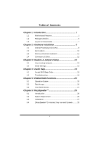
Unit (CPU 8 2.2 Fan Headers 10 2.3 Memory Modules Installation 11 2.4 Connectors, & Slots 12 Chapter 3: Headers & Jumpers Setup 13 3.1 How to setup Jumpers 13 3.2 Detail Settings 13 Chapter 4: Useful Help 19 4.1 Award BIOS Beep Code 19 4.2 Troubleshooting 19 Chapter - Biostar NF4UL-A9 | NF4UL-A9 user's manual - Page 3
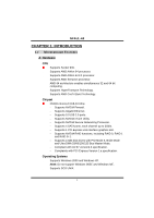
NF4UL-A9 CHAPTER 1: INTRODUCTION 1.1 MOTHERBOARD FEATURES A. Hardware CPU Supports Socket 939. • Supports AMD Athlon 64 processor. • Supports AMD Athlon 64 FX processor. • Supports AMD Sempron processor. • AMD 64 architecture enables simultaneous 32 and 64 bit computing. • Supports HyperTransport - Biostar NF4UL-A9 | NF4UL-A9 user's manual - Page 4
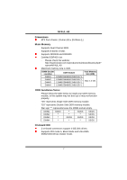
29.35cm (L) Main Memory • Supports Dual Channel DDR. • Supports 8 banks in total. Supports DDR333 and DDR400. Certified DDR400 List: - Please check the website: http://www.biostar.com.tw/products/mainboard/board.php3? name=NF4UL-A9 Maximum memory size is 4GB. DIMM Socket Location DIMM1 DIMM2 - Biostar NF4UL-A9 | NF4UL-A9 user's manual - Page 5
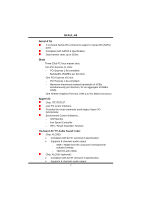
NF4UL-A9 Serial ATA 4 on-board Serial ATA connectors support 4 serial ATA (SATA) ports. Compliant with SATA2.0 specification. "Smart Guardian" function On-board AC'97 Audio Sound Codec Chip: ALC850: Compliant with AC'97 version2.3 specification. Supports 8 channels audio output - SNR > 95dB meet the - Biostar NF4UL-A9 | NF4UL-A9 user's manual - Page 6
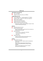
NF4UL-A9 IEEE 1394A Chip (optional) Chip: VIA VT6307. Supports 2 ports with transfer up to 400Mb/s. Gigabit Ethernet LAN NVIDIA Gigabit MAC + VITESSE Gigabit PHY VSC8201. Supports 10 Mb/s, 100 Mb/s and 1Gb/s auto-negotiation. Half/Full duplex capability. Supports personal Firewall setup. Supports - Biostar NF4UL-A9 | NF4UL-A9 user's manual - Page 7
NF4UL-A9 Internal On-board Connectors and Headers 1 audio-out header supports audio-out facilities. • 1 front panel header supports front panel facilities. 1 CD-in connector supports CD-ROM audio-in function. • 1 SPDIF-out connector supports digital audio-out function. • 1 SPDIF-in connector - Biostar NF4UL-A9 | NF4UL-A9 user's manual - Page 8
NF4UL-A9 • 3 audio ports support 6 channels audio-out facilities (with ALC655, optional). PS/2 Mouse Printer Port 1394 Port (optional) LAN Connector Line-in/Rear Line-out PS/2 Keyboard COM1 COM2 (optional) USB *2 USB *2 MIC-in/ Center/ Left B. BIOS & Software BIOS Award legal BIOS. - Biostar NF4UL-A9 | NF4UL-A9 user's manual - Page 9
NF4UL-A9 1.3 LAYOUT & COMPONENTS JKBMS1 JCOM1 JKBMSV1 COM1 CPU1 JCFAN1 JATXPWR1 Socket 939 JPRNT1 COM2 DIMM2 DIMM4 DIMM1 DIMM3 JCOM2 (optional) J1394_USB1 J1394_USBV1 JATXPWR2 JUSBLAN1 EARPHONEJACK1 JAUDIO2 nForce4 (optional) BIOS JPANEL1 BAT1 JSFAN1 Note: ■ represents the 1st pin - Biostar NF4UL-A9 | NF4UL-A9 user's manual - Page 10
NF4UL-A9 CHAPTER 2: HARDWARE INSTALLATION 2.1 CENTRAL PROCESSING UNIT (CPU) Step 1: Pull the lever sideways away from the socket and then raise the lever up to a 90-degree angle. Step 2: Look for the black cut edge on socket, and the white dot on CPU should point forwards this black cut edge. The - Biostar NF4UL-A9 | NF4UL-A9 user's manual - Page 11
NF4UL-A9 Step 3: Hold the CPU down firmly, and then close the lever to complete the installation. Step 4: Put the CPU Fan on the CPU and buckle it. Connect the CPU FAN power cable to the JCFAN1. This completes the installation. 9 - Biostar NF4UL-A9 | NF4UL-A9 user's manual - Page 12
NF4UL-A9 2.2 FAN HEADERS CPU FAN Power Header: JCFAN1 Pin Assignment 1 Ground 3 1 2 +12V 3 FAN RPM FAN RPM rate sense Note: The JCFAN1, JSFAN1and JNBFAN1 support system cooling fan with Smart Fan Control utility. It supports 3 pin head connector. When connecting with wires onto connectors - Biostar NF4UL-A9 | NF4UL-A9 user's manual - Page 13
NF4UL-A9 2.3 MEMORY MODULES INSTALLATION 2.2.1 DDR Module installation 1. Unlock a DIMM slot by pressing the retaining clips outward. Align a DIMM on the slot such that the notch on the DIMM matches the - Biostar NF4UL-A9 | NF4UL-A9 user's manual - Page 14
NF4UL-A9 2.4 CONNECTORS, & SLOTS Floppy Disk Connector: FDD1 The motherboard provides a standard floppy disk connector that supports 360K, 720K, 1.2M, 1.44M and 2.88M floppy disk types. This connector supports the provided floppy drive ribbon cables. Hard Disk Connectors: IDE1/IDE2 The motherboard - Biostar NF4UL-A9 | NF4UL-A9 user's manual - Page 15
NF4UL-A9 CHAPTER 3: HEADERS & JUMPERS SETUP 3.1 HOW TO SETUP JUMPERS The 20-pin power connector on the ATX power supply. JATXPWR2: By connecting this connector, it will provide +12V to CPU power circuit. 13 1 Pin Assignment Pin Assignment 1 +3.3V 13 +3.3V 2 +3.3V 14 -12V 3 Ground - Biostar NF4UL-A9 | NF4UL-A9 user's manual - Page 16
NF4UL-A9 Power Source Headers for ) are powered with +5V standby voltage. Note: In order to support this function "Power-on system via USB device," "J1394_USBV1/JUSBV1" jumper from the variety devices, like CD-ROM, DVD-ROM, PCI sound card, PCI TV turner card etc.. 4 1 JCDIN1 Pin Assignment 1 - Biostar NF4UL-A9 | NF4UL-A9 user's manual - Page 17
NF4UL-A9 Front Panel Audio-out Header: JAUDIO2 This connector will allow user to connect with the front audio out put headers on the PC case. It will disable the output on back panel audio connectors. With ALC850 Audio Sound Codec: 12 13 Pin Assignment 1 Mic in/Stereo MIC-in R. 3 Stereo MIC-in - Biostar NF4UL-A9 | NF4UL-A9 user's manual - Page 18
NF4UL-A9 Digital Audio-out Connector: JSPDIF_OUT This connector will allow user to connect the PCI bracket SPDIF output header. Pin Assignment 1 +5V 3 1 JSPDIF_OUT 2 SPDIF OUT 3 Ground - Biostar NF4UL-A9 | NF4UL-A9 user's manual - Page 19
NF4UL-A9 Header for Front Panel Facilities: JPANEL1 This 24-pin connector includes Power-on, Reset, HDD LED, Power LED, Sleep button, speaker and IrDA Connection. It - Biostar NF4UL-A9 | NF4UL-A9 user's manual - Page 20
NF4UL-A9 Close CMOS Header: JCMOS1 By placing the jumper on pin2-3, it allows user to restore the BIOS safe setting and the CMOS data, please carefully follow the procedures to avoid damaging the motherboard. JCMOS1 Assignment 1 3 Pin 1-2 close Normal Operation (Default). 1 3 Pin 2-3 close - Biostar NF4UL-A9 | NF4UL-A9 user's manual - Page 21
NF4UL-A9 CHAPTER 4: USEFUL HELP 4.1 AWARD BIOS BEEP CODE Beep Sound Meaning One long beep followed by two short Video card not found or video card beeps memory bad High-low siren sound CPU overheated System will shut down automatically One Short beep when system boot-up No error found - Biostar NF4UL-A9 | NF4UL-A9 user's manual - Page 22
NF4UL-A9 CHAPTER 5: NVIDIA RAID FUNCTIONS 5.1 OPERATION SYSTEM Windows XP home Edition Windows XP Professional Edition Windows 2000 Professional 5.2 RAID ARRAYS NVRAID supports the following types of RAID arrays: RAID 0: RAID 0 defines a disk striping scheme that improves disk read and writes times - Biostar NF4UL-A9 | NF4UL-A9 user's manual - Page 23
NF4UL-A9 5.3 HOW RAID WORKS RAID 0: The controller "stripes" data across multiple drives in a RAID 0 array system. It breaks up a large file into smaller blocks and performs - Biostar NF4UL-A9 | NF4UL-A9 user's manual - Page 24
NF4UL-A9 RAID 1: Every read and write is actually carried out in parallel across 2 can be applied for high-availability solutions, or as a form of automatic backup that eliminates tedious manual backups to more expensive and less reliable media. nVIDIA nForce 4 CK8-04 Ultra Block 1 Block - Biostar NF4UL-A9 | NF4UL-A9 user's manual - Page 25
NF4UL-A9 RAID 0+1: RAID 0 drives can be mirrored suing RAID 1 techniques. Resulting in a RAID 0+1 solution for improved performance plus resiliency. nVIDIA nForce 4 CK8-04 Ultra Block 1 Block 3 - Biostar NF4UL-A9 | NF4UL-A9 user's manual - Page 26
NF4UL-A9 Spanning (JBOD): JBOD stands for "Just a Bunch of Disks". Each drive is accessed concurrently. Fault Tolerance: Yes. ※ For more detailed setup information, please refer to the Driver CD, or go to http://www.nvidia.com/page/pg_20011106217193.html to download NVIDIA nForce Tutorial Flash. 24 - Biostar NF4UL-A9 | NF4UL-A9 user's manual - Page 27
NF4UL-A9 25 - Biostar NF4UL-A9 | NF4UL-A9 user's manual - Page 28
NF4UL-A9 CHAPTER 6: WARPSPEEDER™ 6.1 INTRODUCTION [WarpSpeeder™], a new powerful control utility, features three user-friendly functions including Overclock Manager, Overvoltage Manager, and Hardware Monitor. With the Overclock Manager, users can easily adjust the frequency they prefer or they can - Biostar NF4UL-A9 | NF4UL-A9 user's manual - Page 29
NF4UL-A9 6.3 1. INSTALLATION Execute the setup execution file, and then the following dialog will pop up. Please click "Next" Finish" button. Usage: The following figures are just only for reference, the screen printed in this user manual will change according to your motherboard on hand. 27 - Biostar NF4UL-A9 | NF4UL-A9 user's manual - Page 30
NF4UL-A9 6.4 [WARPSPEEDER™] INCLUDES 1 TRAY ICON AND 5 PANELS 1. Tray Icon: Whenever the Tray Icon utility is launched, it will display a little tray icon on the right side - Biostar NF4UL-A9 | NF4UL-A9 user's manual - Page 31
NF4UL-A9 2. Main Panel If you click the tray icon, [WarpSpeeder™] utility will be invoked. Please refer to the following figure; the utility's first window you will see is Main Panel. Main Panel contains features as follows: a. Display the CPU Speed, CPU external clock, Memory clock, AGP clock, and - Biostar NF4UL-A9 | NF4UL-A9 user's manual - Page 32
NF4UL-A9 3. Voltage Panel Click the Voltage button in Main Panel, the button will be highlighted and the Voltage Panel will slide out to up as the following figure. In this panel, you can decide to increase CPU core voltage and Memory voltage or not. The default setting is "No". If you want to get - Biostar NF4UL-A9 | NF4UL-A9 user's manual - Page 33
NF4UL-A9 4. Overclock Panel Click the Overclock button in Main Panel, the button will be highlighted and the Overclock Panel will slide out to left as the following figure. Overclock Panel contains the these features: a. "-3MHz button", "-1MHz button", "+1MHz button", and "+3MHz button": provide - Biostar NF4UL-A9 | NF4UL-A9 user's manual - Page 34
NF4UL-A9 c. "Auto-overclock button": User can click this button and [WarpSpeeder™] will set the according to the Recovery Dialog's setting. Note: Because the testing programs, invoked in Auto-overclock and Verify, include DirectDraw, Direct3D and DirectShow tests, the DirectX 8.1 or newer runtime - Biostar NF4UL-A9 | NF4UL-A9 user's manual - Page 35
NF4UL-A9 6. About Panel Click the "about" button in Main Panel, the button will be highlighted and the About Panel will slide out to up as the following figure. In this panel, you can get model name and detail information in hints of all the chipset that are related to overclocking. You can also - Biostar NF4UL-A9 | NF4UL-A9 user's manual - Page 36
NF4UL-A9 Note: Because the overclock, overvoltage, and hardware monitor features are controlled by several separate chipset, [WarpSpeeder™] divide these features to separate panels. If one chipset is not on board, - Biostar NF4UL-A9 | NF4UL-A9 user's manual - Page 37
NF4UL-A9 2/15, 2005 35
-
 1
1 -
 2
2 -
 3
3 -
 4
4 -
 5
5 -
 6
6 -
 7
7 -
8
-
9
-
10
-
11
-
12
-
13
-
14
-
15
-
16
-
17
-
18
-
19
-
20
-
21
-
22
-
23
-
24
-
25
-
26
-
27
-
28
-
29
-
30
-
31
-
32
-
33
-
34
-
35
-
36
-
37
 |
 |

NF4UL-A9
i
FCC Information and Copyright
This equipment has been tested and found to comply with the limits of a Class
B digital device, pursuant to Part 15 of the FCC Rules. These limits are designed
to provide reasonable protection against harmful interference in a residential
installation. This equipment generates, uses and can radiate radio frequency
energy and, if not installed and used in accordance with the instructions, may
cause harmful interference to radio communications. There is no guarantee
that interference will not occur in a particular installation.
The vendor makes no representations or warranties with respect to the
contents here and specially disclaims any implied warranties of merchantability
or fitness for any purpose. Further the vendor reserves the right to revise this
publication and to make changes to the contents here without obligation to
notify any party beforehand.
Duplication of this publication, in part or in whole, is not allowed without first
obtaining the vendor’s approval in writing.
The content of this user’s manual is subject to be changed without notice and
we will not be responsible for any mistakes found in this user’s manual. All the
brand and product names are trademarks of their respective companies.