Biostar NF4UL-A9 NF4UL-A9 user's manual - Page 20
Close CMOS Header: JCMOS1, Clear CMOS Procedures, Case Open Header: JCI1, Serial ATA Connector: - bios
 |
View all Biostar NF4UL-A9 manuals
Add to My Manuals
Save this manual to your list of manuals |
Page 20 highlights
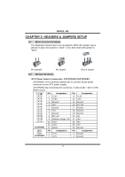
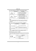
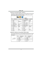
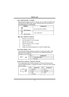
NF4UL-A9 Close CMOS Header: JCMOS1 By placing the jumper on pin2-3, it allows user to restore the BIOS safe setting and the CMOS data, please carefully follow the procedures to avoid damaging the motherboard. JCMOS1 Assignment 1 3 Pin 1-2 close Normal Operation (Default). 1 3 Pin 2-3 close Clear CMOS data. ※ Clear CMOS Procedures: 1. Remove AC power line. 2. Set the jumper to "Pin 2-3 close". 3. Wait for five seconds. 4. Set the jumper to "Pin 1-2 close". 5. Power on the AC. 6. Reset your desired password or clear the CMOS data. Case Open Header: JCI1 This connector allows system to monitor PC case open status. If the signal has been triggered, it will record to the CMOS and show the message on next boot-up. 1 2 JCI1 Pin Assignment 1 Case open signal 2 Ground Serial ATA Connector: JSATA1~JSATA4 The motherboard has a SATA Controller in nForce4 (CK8-04) with 4 channels SATA interface, it satisfies the SATA 1.0 spec and with transfer rate of 1.5Gb/s. Pin Assignment Pin Assignment 1 Ground 2 TX+ 741 3 TX5 RX- 4 Ground 6 RX+ 7 Ground 18
-
 1
1 -
2
-
3
-
4
-
5
-
6
-
7
-
8
-
9
-
10
-
11
-
12
-
13
-
14
-
 15
15 -
 16
16 -
 17
17 -
 18
18 -
 19
19 -
 20
20 -
 21
21 -
 22
22 -
 23
23 -
 24
24 -
 25
25 -
26
-
27
-
28
-
29
-
30
-
31
-
32
-
33
-
34
-
35
-
36
-
37
 |
 |
