Biostar NF4UL-A9 NF4UL-A9 user's manual - Page 16
Power Source Headers for USB Ports: J1394_USBV1/JUSBV1, Power Source Header for PS/2 Keyboard/Mouse
 |
View all Biostar NF4UL-A9 manuals
Add to My Manuals
Save this manual to your list of manuals |
Page 16 highlights
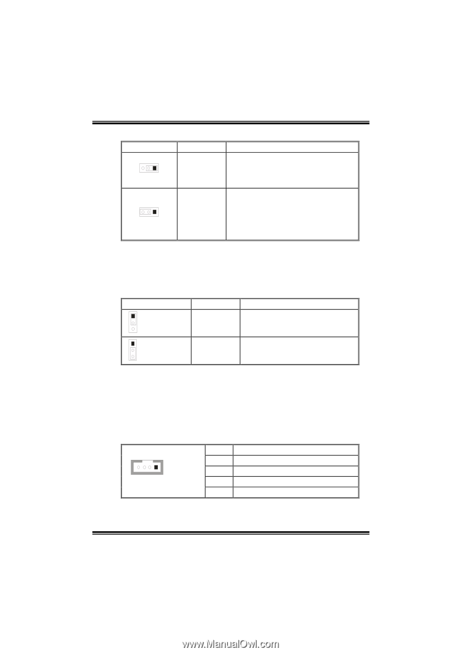
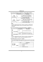
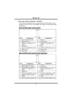
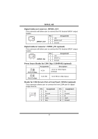
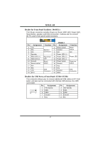
NF4UL-A9 Power Source Headers for USB Ports: J1394_USBV1/JUSBV1 Assignment Description 3 1 +5V Pin 1-2 close J1394_USBV1: +5V for USB ports at J1394_USB1 and JUSBLAN1. JUSBV1: +5V for front USB headers (JUSB1/JUSB2/JUSB3). 3 1 +5V standby Pin 2-3 close Voltage J1394_USBV1: USB ports at J1394_USB1 and JUSBLAN1 are powered with +5V standby voltage. JUSBV1: Front USB headers (JUSB1/JUSB2/JUSB3) are powered with +5V standby voltage. Note: In order to support this function "Power-on system via USB device," "J1394_USBV1/JUSBV1" jumper cap should be placed on Pin 2-3 individually. Power Source Header for PS/2 Keyboard/Mouse: JKBMSV1 Assignment Description 1 +5V 3 Pin 1-2 close +5V for keyboard and mouse 1 +5V Standby PS/2 keyboard and mouse are 3 Pin 2-3 close Voltage powered with +5V standby voltage. Note: In order to support this function "Power-on system via keyboard and mouse", "JKBMSV1" jumper cap should be placed on Pin 2-3. CD-ROM Audio-in Connector: JCDIN1 This connector allows user to connect the audio source from the variety devices, like CD-ROM, DVD-ROM, PCI sound card, PCI TV turner card etc.. 4 1 JCDIN1 Pin Assignment 1 Left channel input 2 Ground 3 Ground 4 Right channel input 14
-
 1
1 -
2
-
3
-
4
-
5
-
6
-
7
-
8
-
9
-
10
-
 11
11 -
 12
12 -
 13
13 -
 14
14 -
 15
15 -
 16
16 -
 17
17 -
 18
18 -
 19
19 -
 20
20 -
 21
21 -
22
-
23
-
24
-
25
-
26
-
27
-
28
-
29
-
30
-
31
-
32
-
33
-
34
-
35
-
36
-
37
 |
 |