Biostar NF4UL-A9 NF4UL-A9 user's manual - Page 12
System Fan Power Header: JSFAN1, North Bridge Fan Power Header: JNBFAN1 - cpu support
 |
View all Biostar NF4UL-A9 manuals
Add to My Manuals
Save this manual to your list of manuals |
Page 12 highlights
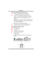
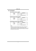
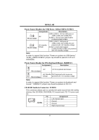
NF4UL-A9 2.2 FAN HEADERS CPU FAN Power Header: JCFAN1 Pin Assignment 1 Ground 3 1 2 +12V 3 FAN RPM rate sense System Fan Power Header: JSFAN1 Pin Assignment 1 Ground 3 1 2 +12V 3 FAN RPM rate sense North Bridge Fan Power Header: JNBFAN1 3 1 Pin Assignment 1 Ground 2 +12V 3 FAN RPM rate sense Note: The JCFAN1, JSFAN1and JNBFAN1 support system cooling fan with Smart Fan Control utility. It supports 3 pin head connector. When connecting with wires onto connectors, please note that the red wire is the positive and should be connected to pin#2, and the black wire is Ground and should be connected to GND. 10
-
 1
1 -
2
-
3
-
4
-
5
-
6
-
 7
7 -
 8
8 -
 9
9 -
 10
10 -
 11
11 -
 12
12 -
 13
13 -
 14
14 -
 15
15 -
 16
16 -
 17
17 -
18
-
19
-
20
-
21
-
22
-
23
-
24
-
25
-
26
-
27
-
28
-
29
-
30
-
31
-
32
-
33
-
34
-
35
-
36
-
37
 |
 |

NF4UL-A9
10
2.2
F
AN
H
EADERS
CPU FAN Power Header: JCFAN1
Pin
Assignment
1
Ground
2
+12V
1
3
3
FAN RPM rate sense
System Fan Power Header: JSFAN1
Pin
Assignment
1
Ground
2
+12V
1
3
3
FAN RPM rate sense
North Bridge Fan Power Header: JNBFAN1
Pin
Assignment
1
Ground
2
+12V
1
3
3
FAN RPM rate sense
Note:
The JCFAN1, JSFAN1and JNBFAN1 support system cooling fan with
Smart Fan Control utility. It supports 3 pin head connector. When
connecting with wires onto connectors, please note that the red wire is the
positive and should be connected to pin#2, and the black wire is Ground
and should be connected to GND.