Biostar TG31-A7 Setup Manual
Biostar TG31-A7 Manual
 |
View all Biostar TG31-A7 manuals
Add to My Manuals
Save this manual to your list of manuals |
Biostar TG31-A7 manual content summary:
- Biostar TG31-A7 | Setup Manual - Page 1
TG31-A7 Setup Manual FCC Information and Copyright This equipment has been tested and found to can radiate radio frequency energy and, if not installed and used in accordance with the instructions, may cause harmful interference to radio communications. There is no guarantee that interference will - Biostar TG31-A7 | Setup Manual - Page 2
12 3.2 Detail Settings 12 Chapter 4: T-Series BIOS & Software 19 4.1 T-Series BIOS 19 4.2 T-Series Software 27 Chapter 5: Useful Help 32 5.1 Driver Installation Note 32 5.2 Extra Information 33 5.3 AMI BIOS Beep Code 34 5.4 Troubleshooting 35 Appendencies: SPEC In Other Language 36 German - Biostar TG31-A7 | Setup Manual - Page 3
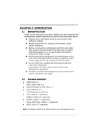
TG31-A7 1.1 BEFORE YOU START Thank you for choosing our product. Before you start installing the motherboard, please make sure you follow the instructions Rear I/O Panel for ATX Case X 1 User's Manual X 1 Fully Setup Driver CD X 1 FDD Cable X 1 (optional) USB 2.0 Cable X1 (optional) S/PDIF Cable X 1 - Biostar TG31-A7 | Setup Manual - Page 4
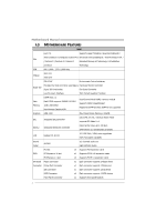
Motherboard Manual 1.3 MOTHERBOARD FEATURES SPEC LGA 775 Supports Hyper-Threading / Execute Disable Bit / Intel Core2Duo / Core2Quad / Celeron 4xx Enhanced Intel SpeedStep® / Intel Architecture-64 / CPU / Pentium D / Pentium 4 / Celeron D Extended Memory 64 Technology / Virtualization - Biostar TG31-A7 | Setup Manual - Page 5
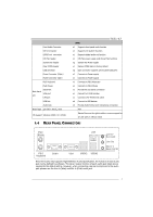
Panel I/O Serial Port VGA port LAN port USB Port Audio Jack Board Size 210 (W) x 305 (L) mm OS Support Windows 2000 / XP / VISTA TG31-A7 SPEC x1 Supports front panel audio function x1 Supports CD audio-in function x1 Supports digital audio out function x1 CPU Fan power supply (with Smart Fan - Biostar TG31-A7 | Setup Manual - Page 6
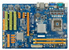
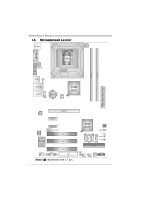
Motherboard Manual 1.5 MOTHERBOARD LAYOUT JCFAN1 JKBMS1 LGA775 CPU1 JATXPWR1 JCOM1 JVGA1 DDR2_A1 DDR2_B1 JUSB1 I/O JAUDIOF1 JPRNT1 PCI3 FDD1 Note: ■ represents the 1st pin. Int el ICH7 BIOS JCMOS1 SATA1 SATA3 LE D2 LE D1 PWRSW1 SATA2 RSTSW2 SATA4 IDE1 JUSBV2 JSFAN1 JPANEL1 JUSB2 - Biostar TG31-A7 | Setup Manual - Page 7
CHAPTER 2: HARDWARE INSTALLATION TG31-A7 2.1 INSTALLING CENTRAL PROCESSING UNIT (CPU) Special Notice: Remove Pin Cap before installation, and make good preservation for future use. When the CPU is removed, cover the Pin Cap on the empty socket to ensure pin legs won't be damaged. Pin Cap Step 1: - Biostar TG31-A7 | Setup Manual - Page 8
Motherboard Manual Step 2: Look for the triangular cut edge on socket, and the golden dot on CPU should point forwards this triangular cut edge. The CPU will fit only in the correct orientation. Step 2-1: Step 2-2: Step 3: Hold the CPU down firmly, and then lower the lever to locked position to - Biostar TG31-A7 | Setup Manual - Page 9
TG31-A7 2.2 FAN HEADERS These fan headers support cooling-fans built in the computer. The fan cable and connector may be different according to the fan manufacturer. Connect the fan cable to the connector while matching the black wire to pin#1. JCFAN1: CPU Fan Header 1 4 Pin Assignment 1 - Biostar TG31-A7 | Setup Manual - Page 10
DDR2_A1 DDR2_B1 Motherboard Manual 2.3 INSTALLING SYSTEM MEMORY A. Memory Modules 1. Unlock a DIMM slot by pressing the retaining clips outward. Align a DIMM on the slot such that the notch on the - Biostar TG31-A7 | Setup Manual - Page 11
B. Memory Capacity TG31-A7 DIMM Socket Location DDR2_A1 DDR2_B1 DDR Module 256MB/512MB/1GB/2GB 256MB/512MB/1GB/2GB Total Memory Size Max is 4B. C. Dual Channel Memory installation To trigger the Dual Channel function of the motherboard, the memory module must meet the following requirements: - Biostar TG31-A7 | Setup Manual - Page 12
Motherboard Manual 2.4 CONNECTORS AND SLOTS FDD1: Floppy Disk Connector The motherboard provides a standard floppy disk connector that supports 360K, 720K, 1.2M, 1.44M and 2.88M floppy disk types. This connector supports the provided floppy drive ribbon cables. 2 34 1 33 IDE1: Hard Disk - Biostar TG31-A7 | Setup Manual - Page 13
TG31-A7 PEX16_1: PCI-Express x16 per direction, for an aggregate of 500MB/s totally. - PCI-Express supports a raw bit-rate of 2.5GB/s on the data pins. - PEX16_1 PEX1_1 PEX1_2 PCI1~PCI3: Peripheral Component Interconnect Slots This motherboard is equipped with 3 standard PCI slots. PCI stands for - Biostar TG31-A7 | Setup Manual - Page 14
Motherboard Manual CHAPTER 3: HEADERS & JUMPERS SETUP 3.1 HOW TO SETUP JUMPERS The illustration shows how to set up jumpers. When the jumper cap is placed on pins, the - Biostar TG31-A7 | Setup Manual - Page 15
TG31-A7 JATXPWR2: ATX Power Source Connector This connector allows user to connect 11 +12V 12 +3.3V JATXPWR1: ATX Power Source Connector By connecting this connector, it will provide +12V to CPU power circuit. 4 3 1 2 Pin Assignment 1 +12V 2 +12V 3 Ground 4 Ground Note: Before power - Biostar TG31-A7 | Setup Manual - Page 16
Motherboard Manual JUSB2/JUSB3: Headers for USB 2.0 Ports at Front Panel This header allows user to connect additional USB cable on the PC front panel, and also can be connected with internal USB devices, like USB like CD-ROM, DVD-ROM, PCI sound card, PCI TV turner card etc.. Pin Assignment 4 1 - Biostar TG31-A7 | Setup Manual - Page 17
TG31-A7 JCMOS1: Clear CMOS Header By placing the jumper on pin2-3, it allows user to restore the BIOS safe setting and the CMOS data, please carefully follow the procedures to avoid damaging the motherboard. 13 Pin 1-2 Close: Normal Operation (default). 13 13 Pin 2-3 Close: Clear CMOS data. ※ - Biostar TG31-A7 | Setup Manual - Page 18
Motherboard Manual JSPDIF_OUT1: Digital Audio-out Connector This connector allows user to connect the PCI bracket SPDIF output header. 13 Pin Assignment 1 +5V 2 SPDIF_OUT 3 Ground JUSBV1/JUSBV2: Power Source Headers for USB Ports Pin 1-2 Close: JUSBV1: +5V for USB ports at JUSB1/JRJ45USB1. - Biostar TG31-A7 | Setup Manual - Page 19
JPRNT1: Printer Port Connector This header allows you to connector printer on the PC. TG31-A7 2 1 Pin Assignment 1 -Strobe 2 -ALF 3 Data 0 4 -Error 5 Data 1 6 -Init 7 Data 2 8 -Scltin 9 Data 3 10 Ground 11 Data 4 12 Ground 13 Data 5 25 Pin Assignment 14 Ground 15 - Biostar TG31-A7 | Setup Manual - Page 20
Motherboard Manual On-Board LED Indicators There are 2 LED indicators on the motherboard to show system status. LED2 LED1 LED1 and LED2: These 2 LED indicate system power on diagnostics. Please refer to the table below for different messages: - Biostar TG31-A7 | Setup Manual - Page 21
CHAPTER 4: T-SERIES BIOS & SOFTWARE 4.1 T-SERIES BIOS TG31-A7 T-Series BIOS Features Overclocking Navigator Engine (O.N.E.) Memory Integration Test (M.I.T., under Overclock Navigator Engine) BIO-Flasher: Update BIOS file from USB Flash Drive or FDD Self Recovery System (S.R.S) Smart Fan - Biostar TG31-A7 | Setup Manual - Page 22
Motherboard Manual Manual Overclock System (M.O.S.) MOS is designed for experienced overclock users. It allows users to customize personal overclock settings. Main Advanced PCIPnP BIOS SETUP UTILITY Boot Chipset T-Series Exit T-Series Settings Options WARNING: Setting wrong values in - Biostar TG31-A7 | Setup Manual - Page 23
TG31-A7 FSB Voltage This function will increase chipset stability when overclocking. Chipset Voltage This function will increase chipset stability when overclocking. Memory Voltage This function will increase memory stability when overclocking. DRAM Frequency To get better system performance, - Biostar TG31-A7 | Setup Manual - Page 24
Motherboard Manual V6 Tech Engine This engine will make a good over-clock performance. Main Advanced PCIPnP BIOS SETUP UTILITY Boot Chipset T-Series Exit T-Series Settings WARNING: Setting wrong values in below sections may cause system to malfunction. OverClock Navigator [Automate - Biostar TG31-A7 | Setup Manual - Page 25
TG31-A7 Notices: Not all types of Intel CPU perform above overclock setting ideally; the difference will be based on the selected CPU model. B. Memory Integration Test (M.I.T.) This function is under "Overclocking Navigator Engine" item. MIT allows users to test memory compatibilities, and no - Biostar TG31-A7 | Setup Manual - Page 26
the Power-On Self Tests (POST) procedure while booting up. Updating BIOS with BIO-Flasher 1. Go to the website to download the latest BIOS file for the motherboard. 2. Then, save the BIOS file into a USB pen drive or a floppy disk. 3. Insert the USB pen drive or the floppy disk that contains the - Biostar TG31-A7 | Setup Manual - Page 27
overheat problem and maintain the system temperature at a safe level. Main Advanced PCIPnP BIOS SETUP UTILITY Boot Chipset T-Series Exit Advanced Settings WARNING: Setting wrong values in below sections may cause system to malfunction. > CPU Configuration > SuperIO Configuration > Hardware - Biostar TG31-A7 | Setup Manual - Page 28
Motherboard Manual Smart Fan Calibration Choose this item and then the BIOS will automatically test and detect the CPU/System fan functions and show CPU/System fan speed. Control Mode This item provides several operation modes of the fan. Fan Ctrl OFF(℃) If the CPU/System temperature is lower than - Biostar TG31-A7 | Setup Manual - Page 29
-screen instructions to complete the installation. Launching T-Series Software After the installation process, you will see the software icon "HW Monitor"/ "eHOT Line" / "Tseries BIOS Update" appears on the desktop. Double-click the icon to launch T-Series utility. Hardware Monitor HW Monitor is - Biostar TG31-A7 | Setup Manual - Page 30
Motherboard Manual eHot-Line (Optional) eHot-Line is a convenient utility that helps you to contact with our Tech-Support system. This utility will collect the system information which is useful for analyzing the problem you may have encountered, and then send these information to our tech-support - Biostar TG31-A7 | Setup Manual - Page 31
the file name and then click "Save". Your system information will be saved to a .txt file. TG31-A7 Open the saved .txt file, you will see your system information including motherboard/BIOS/CPU/video/ device/OS information. This information is also concluded in the sent mail. We will not share - Biostar TG31-A7 | Setup Manual - Page 32
Motherboard Manual BIOS Update BIOS Update is a convenient utility which allows you to update your motherboard BIOS under Windows system. AWARD BIOS Show current BIOS information AMI BIOS Clear CMOS function (Only for AWARD BIOS) Save current BIOS to a .bin file Update BIOS with a BIOS file < - Biostar TG31-A7 | Setup Manual - Page 33
TG31-A7 Before doing this, please download the proper BIOS file from the website. For AWARD BIOS, update BIOS procedure should be run with Clear CMOS function, so please check on Clear CMOS first. Then click Update BIOS button, a dialog will show for asking you backup current BIOS. - Biostar TG31-A7 | Setup Manual - Page 34
for better system performance. You will see the following window after you insert the CD The setup guide will auto detect your motherboard and operating system. Note: If this window didn't show up after you insert the Driver CD, please use file browser to locate and execute the file SETUP.EXE under - Biostar TG31-A7 | Setup Manual - Page 35
TG31-A7 5.2 EXTRA INFORMATION CPU Overheated If the system shutdown automatically after power on system for seconds, that means the CPU protection function has been activated. When the CPU is over heated, the motherboard will shutdown automatically to avoid a damage of the CPU, and the system may - Biostar TG31-A7 | Setup Manual - Page 36
video adapter) Troubleshooting POST BIOS Beep Codes Number of Beeps Troubleshooting Action 1, 3 Reseat the memory, or replace with known good modules. Fatal error indicating a serious problem with the system. Consult your system manufacturer. Before declaring the motherboard beyond all hope - Biostar TG31-A7 | Setup Manual - Page 37
TG31-A7 5.4 TROUBLESHOOTING Probable Solution 1. No power to the system at all 1. Make sure power cable is Power light don't illuminate, fan securely plugged in. inside power supply does not turn 2. Replace cable. on. 3. Contact technical support "CMOS Failure." Review system's equipment. - Biostar TG31-A7 | Setup Manual - Page 38
Motherboard Manual APPENDENCIES: SPEC IN OTHER LANGUAGE GERMAN Spezifikationen LGA 775 Unterstützt Hyper-Threading / Execute Disable Bit / Intel Core2Duo / Core2Quad / Celeron 4xx Enhanced IntelSpeedStep® / IntelArchitecture-64 / CPU / Pentium 4 / Pentium D / Celeron D Extended Memory 64 - Biostar TG31-A7 | Setup Manual - Page 39
Tastatur PS/2-Maus Serieller Anschluss Rückseiten-E VGA-Anschluss /A LAN-Anschluss USB-Anschluss Audioanschluss Platinengröße 210 mm (B) X 305 mm (L) OS-Unterstüt Windows 2000 / XP / VISTA zung TG31-A7 Spezifikationen x1 Jeder Anschluss unterstützt 2 Diskettenlaufwerke x1 Jeder Anschluss unterst - Biostar TG31-A7 | Setup Manual - Page 40
Motherboard Manual FRANCE SPEC LGA 775 Prend en charge les technologies Hyper-Threading / Processeurs Intel Core2Duo / Core2Quad d'exécution de bit de désactivation / Intel SpeedStep® UC / Celeron 4xx / Pentium 4 / - Biostar TG31-A7 | Setup Manual - Page 41
TG31-A7 SPEC Connecteur de disquette Chaque connector prend en charge 2 lecteurs Port LAN x1 Port USB x4 Fiche audio x3 Dimensions 210 mm (l) X 305 mm (H) ATX de la carte Support SE Windows 2000 / XP / VISTA Biostar se réserve le droit d'ajouter ou de supprimer le support de SE avec ou - Biostar TG31-A7 | Setup Manual - Page 42
Motherboard Manual ITALIAN SPECIFICA LGA 775 Supporto di Hyper-Threading / Execute Disable CPU Processore Intel Core2Duo / Bit / Enhanced Intel SpeedStep® dell'ambiente: Fornisce le funzionalità legacy Super Monitoraggio hardware Super I/O I/O usate più comunemente. Controller / - Biostar TG31-A7 | Setup Manual - Page 43
TG31-A7 SPECIFICA Connettore ventolina CPU su scheda x1 Supporta la funzione d'output audio digitale Alimentazione ventolina CPU ( USB x4 Connettore audio x3 Dimension 210 mm (larghezza) x 305 mm i scheda (altezza) ATX Sistemi Biostar si riserva il diritto di aggiungere o operativi Windows - Biostar TG31-A7 | Setup Manual - Page 44
Motherboard Manual SPANISH Especificación LGA 775 Admite Hyper-Threading / Bit de deshabilitación de Procesador Intel Core2Duo / Core2Quad / ejecución / Intel SpeedStep® Mejorado / Intel CPU Monitor hardware uso más común Súper E/S. Controlador/monitor Controlador ATA Serie Integrado Tasas - Biostar TG31-A7 | Setup Manual - Page 45
TG31-A7 Especificación Conector disco flexible X1 Cada conector soporta 2 serie X1 trasero de Puerto VGA X1 E/S Puerto de red local X1 Puerto USB X4 Conector de sonido X3 Tamaño de 210 mm. (A) X 305 Mm. (H) ATX la placa Soporte de sistema Windows 2000 / XP / VISTA operativo Biostar - Biostar TG31-A7 | Setup Manual - Page 46
Motherboard Manual PORTUGUESE ESPECIFICAÇÕES LGA 775 Suporta as tecnologias Hyper-Threading / Execute Processador Intel Core2Duo / CPU Disable Pin Count). Iniciativas para controlo do ambiente Monitorização do hardware Controlador/Monitor da velocidade da ventoinha Função "Smart Guardian" da - Biostar TG31-A7 | Setup Manual - Page 47
TG31-A7 Conector da ventoinha da CPU x1 na placa Conector da ventoinha do sistema x2 Alimentação da ventoinha da CPU (com a função USB x4 Tomada de áudio x3 Tamanho 210 mm (L) X 305 mm (A) ATX da placa Sistemas A Biostar reserva-se o direito de adicionar ou remover operativos Windows - Biostar TG31-A7 | Setup Manual - Page 48
Motherboard Manual POLISH SPEC LGA 775 Obsługa Hyper-Threading / Execute Disable Bit / Procesor Procesor Intel Core2Duo / warunków pracy, Super I/O Zapewnia najbardziej powszechne funkcje Monitor H/W Super I/O. Kontroler/Monitor prędkości wentylatora Interfejs Low Pin Count Funkcja - Biostar TG31-A7 | Setup Manual - Page 49
TG31-A7 SPEC Złącze napędu dyskietek x1 Każde złącze obsługuje 2 napędy dyskietek Złącze x1 I/O Port LAN x1 Port USB x4 Gniazdo audio x3 Wymiary 210 mm (S) X 305 mm (W) ATX płyty Obsluga systemu Windows 2000 / XP / VISTA operacyjne go Biostar zastrzega sobie prawo dodawania lub odwoł - Biostar TG31-A7 | Setup Manual - Page 50
Motherboard Manual RUSSIAN СПЕЦ CPU LGA 775 Hyper-Threading / Execute Intel Core2Duo / Core2Quad / Disable Bit / Enhanced Intel SpeedStep® / Intel ый Celeron 4xx / Pentium 4 / Pentium D / Architecture-64 / Extended Memory 64 Technology / - Biostar TG31-A7 | Setup Manual - Page 51
x2 CMOS x1 USB 2 USB x2 24 вывод) x1 4 вывод) x1 PS/2 x1 Мышь PS/2 x1 Задняя x1 панель Порт VGA x1 Порт LAN x1 USB-порт x4 ода x3 Размер 210 мм (Ш) X 305 мм (В) ATX панели Windows 2000 / XP / VISTA OS Biostar OS 49 - Biostar TG31-A7 | Setup Manual - Page 52
Motherboard Manual ARABIC Hyper-Threading / Execute Disable Bit LGA 775 Enhanced Intel SpeedStep® / Intel Architecture-64 / Intel Core2Duo / Core2Quad Extended Memory 64 Technology / Virtualization Celeron 4xx / Pentium 4 / - Biostar TG31-A7 | Setup Manual - Page 53
Smart Fan 1 2 1 CMOS USB 2 USB 1 24 1 4 1 PS/2 1 PS/2 1 1 VGA 1 4 USB 3 ATX 210 305 X Biostar Windows 2000 / XP / VISTA 51 - Biostar TG31-A7 | Setup Manual - Page 54
Motherboard Manual JAPANESE 仕様 LGA 775 Hyper-Threading / Execute Disable Bit / Enhanced Intel Intel Core2Duo / Core2Quad / Celeron 4xx SpeedStep® / Intel Architecture-64 / Extended CPU / Pentium 4 / Pentium D / Celeron D Memory 64 Technology / Virtualization Technologyをサ processor FSB - Biostar TG31-A7 | Setup Manual - Page 55
PS/2マウス I/O VGAポート LANポート USBポート 210 mm (幅) X 305 mm (高さ) OS Windows 2000 / XP / VISTA TG31-A7 仕様 x1 2 x1 1 x1 2つのIDE x4 1つのSATA x1 x1 x1 CD x1 x1 CPU x2 x1 2 USB x2 ます x1 x1 x1 x1 x1 x1 x1 x4 x3 ATX Biostar OS 2008/03/26
-
 1
1 -
 2
2 -
 3
3 -
 4
4 -
 5
5 -
 6
6 -
 7
7 -
8
-
9
-
10
-
11
-
12
-
13
-
14
-
15
-
16
-
17
-
18
-
19
-
20
-
21
-
22
-
23
-
24
-
25
-
26
-
27
-
28
-
29
-
30
-
31
-
32
-
33
-
34
-
35
-
36
-
37
-
38
-
39
-
40
-
41
-
42
-
43
-
44
-
45
-
46
-
47
-
48
-
49
-
50
-
51
-
52
-
53
-
54
-
55
 |
 |

TG31-A7 Setup Manual
FCC Information and Copyright
This equipment has been tested and found to comply with the limits of a Class
B digital device, pursuant to Part 15 of the FCC Rules. These limits are designed
to provide reasonable protection against harmful interference in a residential
installation. This equipment generates, uses, and can radiate radio frequency
energy and, if not installed and used in accordance with the instructions, may
cause harmful interference to radio communications. There is no guarantee
that interference will not occur in a particular installation.
The vendor makes no representations or warranties with respect to the
contents here and specially disclaims any implied warranties of merchantability
or fitness for any purpose. Further the vendor reserves the right to revise this
publication and to make changes to the contents here without obligation to
notify any party beforehand.
Duplication of this publication, in part or in whole, is not allowed without first
obtaining the vendor’s approval in writing.
The content of this user’s manual is subject to be changed without notice and
we will not be responsible for any mistakes found in this user’s manual. All the
brand and product names are trademarks of their respective companies.